|
|

|

|
|||
|
|
|
|
The Job Settings tab in a job contains the variables that affect various aspects of the job during the automation run. There are several sections to these settings.
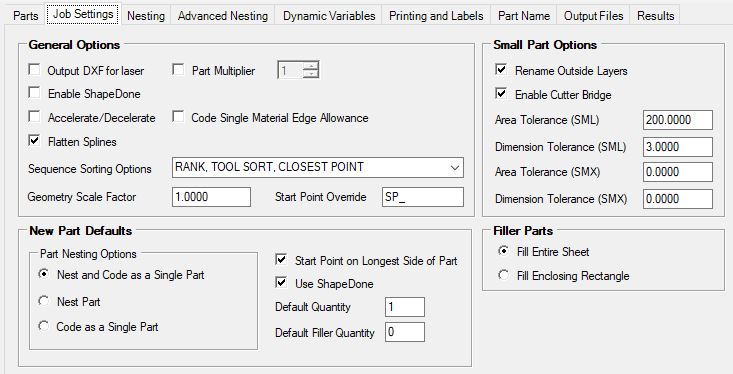
General Options
Output DXF for laser
This option will create a DXF file of each nest or single part cut for a projection laser to use in order to show the layout of the parts on the table. If you do not have a projection laser, leave this option off.
Enable Shape Done
Enabling Shape Done will turn on Shape Done for the job. If parts have the option turned on to enable Shape Done, then a copy of the part will be stored with the knowledge drawing.
Accelerate/Decelerate
Enabling Accelerate/Decelerate will use any cutting knowledge that has the ACC/DEC option selected for machines that need the NC code to slow down and speed up the machine.
Flatten Splines
Splines are special objects in that they have a continuously changing radius. Being such, they must be converted into arc and/or line segments to be able to produce NC code. If the AutoCAD Express Tools are installed, the FLATTEN command is available and Router-CIM will use it to convert the spline. You can also use the command manually in AutoCAD by typing FLATTEN at the command line or through the Express Tools menu or ribbon. If the FLATTEN command is not available, Router-CIM will convert the spline into small line segments for NC processing. If the FLATTEN command is failing to convert the spline, you may want to disable it from being used in Router-CIM Automation Suite.
Enabling Flatten Splines allows Router-CIM to convert the spline feature into arc and/or line segments.
Sequence Sorting Options
You may select from any of the sorting options listed and that option will be used to sort all the parts in the job during Sequence.
The value entered into this field will be used during the Router-CIM Automation Suite job run when the parts is loaded into AutoCAD. For instance, to scale a part drawn in inches to mm, you could use a value of 25.4.
Note: This field will only affect the part drawing itself, cut knowledges and materials will need to be configured for the resulting part size after the scale factor has been applied.
Part Multiplier
The Part Multiplier will multiply the part quantities by the selected value when a job is processed. To activate, check the box and use the up and down arrows to set the part multiplier.
![]()
![]()
Code Single Material Edge Allowance
Enabling Code Single Material Edge Allowance allows for a part that is set to 'Code as Single Part' to have the individual NC code file produced with the Material Edge Allowance that is set up in your Materials Database.
Start Point Override will change the startpoints on geometry in Router-CIM Automation Suite during a job run, you can set it to “SP_” (or any 3 characters) and then rename your layers with that prefix. Once that has been completed, you will need to change the DOIT file layer to knowledge associations in order to cut the layers properly. You can then run the job, Router-CIM Automation Suite will stop on the geometry on those layers and prompt you to pick a start point.
Rename Outside Layers
If this option is active, parts will have the outside layer rename with a prefix of SML or SMX so that an alternate knowledge can be used on them. This is useful if you cut small parts and they tend to lose vacuum or move.
Rename Outside Layers uses two variables. The first is 'Area Tolerance' which is based on the square units of the outside geometry. If the outside geometry is equal to or less then the value, it will be considered an SML or SMX part and the outside layer name will receive the prefix SML or SMX. The second variable checks for the long, narrow parts. A line is drawn at the 'Dimension Tolerance' in X and Y when the part is processed. If the part, as it is oriented, does not intersect the line, it will also be considered an SML part even if the area of the outside geometry is over the Area Tolerance.
The options allows for 2 sets of small parts. SML parts will be defined by 'Area Tolerance (SML)' and 'Dimension Tolerance (SML)'. SMX parts will be defined by 'Area Tolerance (SMX)' and 'Dimension Tolerance (SMX)'
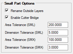
For example, if a part is less then the area for the 'Area Tolerance (SML)' but an area greater than the 'Area Tolerance (SMX)' you have indicated and this part has an outside layer such as OUTSIDE_0.7500, this feature will rename that layer to SMLOUTSIDE_0.7500. This way in the DOIT file you can make knowledge associations to the layer SMLOUTSIDE_0.7500 so that the small parts are machined differently then larger parts. In this same example, if the part has an area of 250 but it is a 4x75 rectangle, it will also rename the outside layer to SMLOUTSIDE_0.7500 because of the dimension tolerance.
Also then if a part is less then the area for the 'Area Tolerance (SMX)' you have indicated and this part has an outside layer such as OUTSIDE_0.7500, this feature will rename that layer to SMXOUTSIDE_0.7500. This way in the DOIT file you can make knowledge associations to the layer SMXOUTSIDE_0.7500 so that the very small parts are machined differently then large or small parts. In this same example, if the part has an area of 150 but it is a 2x75 rectangle, it will also rename the outside layer to SMXOUTSIDE_0.7500 because of the dimension tolerance.
Enable Cutter Bridge
If this option is active any cutting knowledge that has a cutter bridge identified and is used, the cutter bridge amount will be added to the material's bridge width in order to give more material around the specified part.
For more information on setting a cutter bridge in a cut knowledge, refer to the 'Cutter Bridge' section under 'Tool Information'.
New Part Defaults
Part Nesting Options
Nest and Code as Single Part
Checking this option will cause Router-CIM Automation Suite to nest each part in the job, and also make a separate NC program for each and every part on its own. This is useful for situations where a part is later broken or lost, a piece of material can be placed on the machine at the home position and run just the program for the one part.
Nest Part
When enabled, this option will cause Router-CIM Automation Suite to place every part in the job into a nested sheet based on the material specified. If more than one material exists for parts in a job, nests will be created for each sheet with the parts specified for that material.
Code as Single Part
Using this setting will cause Router-CIM Automation Suite to make a separate NC program for each part in a job. No parts will be nested together.
NOTE: For more information about 'Code as Single Part', please visit the 'Part Properties' section.
StartPoint on longest side of part
Using this option will ensure that when new parts are added to a job, the Startpoint on longest side of part box is checked by default.
Checking this box will force Router-CIM Automation Suite to move the startpoint to the longest side of the part, regardless of where the startpoint exists currently.
Use ShapeDone
This option must be turned on in order for a part to be passed to the ShapeDone folder and stored.
NOTE: ShapeDone will become inactive when parts are set to 'Nest and Code as Single Part' or 'Code as Single Part'. For more information on ShapeDone, click here.
Default Quantity
This field allows you to set the default quantity that parts are set to when they are added to a new job. When a new job is created, the number of parts that are set automatically will be set to this number.
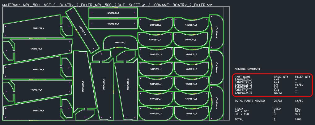
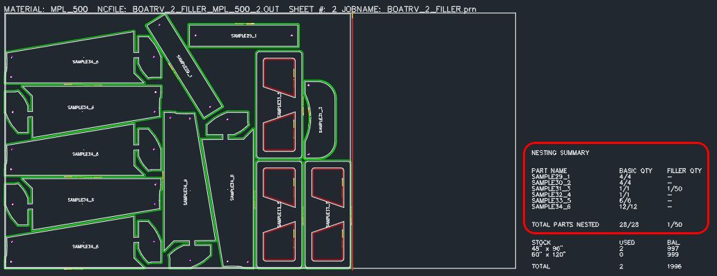
Default Filler Quantity
This parameter is to set the default number of filler parts set for each new part in a job. If there is enough space in the nest, then these parts will be placed in the nest to fill the space and boost sheet yield, up to the number set in this section.
Filler Parts Control
Allows you to set any number of part(s) to use to fill in gaps and open space in the nest.
When a filler part quantity is defined, you can fill the nest based on the sheet size or the enclosing rectangle which is the amount of area used by the nested parts themselves.
Fill Entire Sheet:
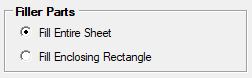
When set to 'Fill Entire Sheet', if filler parts are defined, the scrap settings for the material may be ignored and nesting will fill any left over area on a sheet with filler parts if the quantity allows.
Fill Enclosing Rectangle:
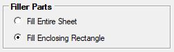
When set to 'Fill Enclosing Rectangle', if filler parts are defined, the scrap settings for the material will not be ignored and nesting will fill any left over area within the enclosing rectangle created by the nested parts.
For more information on how to set the Filler Parts quantity, refer to the 'Part Properties' section.