|
|

|

|
|||
|
|
|
|
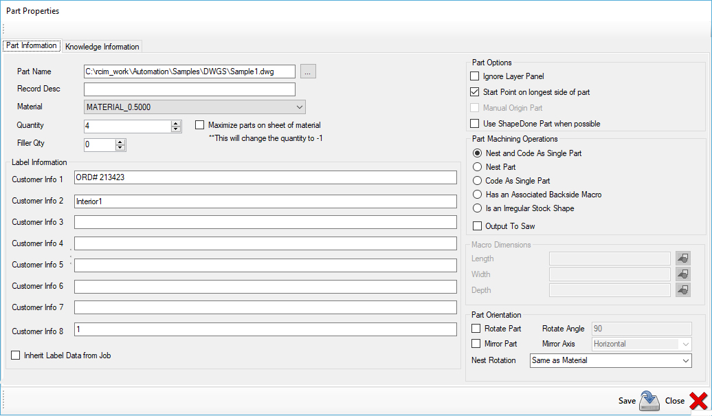
The Part Properties are broken down into two tabs. They are Part Information and Knowledge Information.
Advanced Nesting Users:
If you have the Advanced Nesting Module, you will see an additional section as shown here for the Veneer Match Parameters:
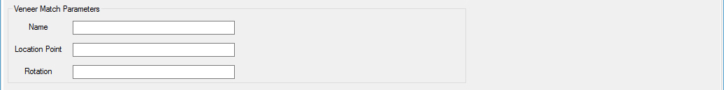
Go to the Veneer Match Parameters section for more information.
Part Information
Path Name
This box displays the path and name of the current selected part.
Record Description (Optional)
An editable field that will allow you to enter information you want to appear in the part description location of a label or a description you want to store in the job for the part if you do not use labels.
Material
Shows the material selected for the current part, and also allows you to change the part material from a drop-down list containing all the materials in your current database.
Quantity
Editable field to display or set the number of the selected part you want to appear in the job.
Maximize parts on sheet of material: If this checkbox is selected, when this part is nested, Router-CIM Automation Suite will change the quantity to -1. This will allow the nesting operation to maximize this part on a full sheet of material.
Filler Quantity (optional)
Allows you to set any number of this part to use to fill in gaps and open space in the nest. Use this option if you can store an extra quantity of the current part. Router-CIM Automation Suite will only generate filler parts if the option to allow them is turned on and there is sufficient room in the nest. No regular required parts from the job will be sacrificed to allow filler parts.
Label Information (optional)
There are 8 editable fields that can contain any data you think relevant to appear on the part labels. You can place data in as many or as few of these as you wish.
Inherit Label Data from Job
It is possible to have this data set to the same values for every part automatically if you set them in a job. This setting in each parts properties to 'Inherit Label Data from Job' will set all the label fields for each part to whatever they were set to in the job that the parts were added to.
Ignore Layer Panel
| When checked, this will ignore the default rectangle for the panel size on a macro, even if there is a layer to knowledge association present for it. It will further ignore that layer for nesting purposes. |
| Start Point on longest side of part |
| If checked, this option will move the start point of the shapes on the currently selected part to the mid point of whichever element on that particular shape is the longest, whether that is a line or an arc. |
Manual Origin Part
This option is for Router-CIM macros only and will allow you to set where the origin of the part is instead of assuming 0,0.
Use ShapeDone Part when possible
Checking this option will allow the ShapeDone feature to be used on the selected part. Once the part is cut, that part and tool paths will be placed in the ShapeDone folder so that if it is cut at a later time, and has not been modified, it will simply be passed directly to nest and will not be cut again.
Nest and Code As Single Part
This option will allow all the parts in a job to have code created not only for the nests, but it will also generate one NC code file for each individual part in the job. See information below under 'Code as Single Part' if you want the individual NC code file to be offset by the materials edge allowance.
Nest Part
This will cause the parts in the job to be nested on the specified material.
Code As Single Part
Any part with this option checked will be cut and have code made for just the one part and it will not be considered for nesting. If you would like to have the part offset by the materials edge allowance like is done during the nesting process, please refer to the 'Code Single Material Edge Allowance' section. In order to use this feature, the outside geometry of the part must be on a layer defined under the Layer Lists in your 'General Settings'.
Has an Associated Backside Macro
This option is for Router-CIM macros only and will cause Router-CIM Automation Suite to look for a macro with the same name, followed by -b. The backside macro will then be cut as a single part (not nested) and the code included in the results folder. For instance Style1.scn has a backside macro named Style1-b.scn.
If Style1.scn were a part in a job, you could check this option and both Style1.scn and Style1-b.scn would be cut, but only Style1.scn would be nested. The code for Style1-b.scn would be as a single part.
Is an Irregular Stock Shape
A drawing that has geometry on layer IR_STOCK can be placed in a job and then if this option is checked, that shape would be used as a piece of material for nesting. Any shape is allowed, but it should be a closed polyline (on layer IR_STOCK).
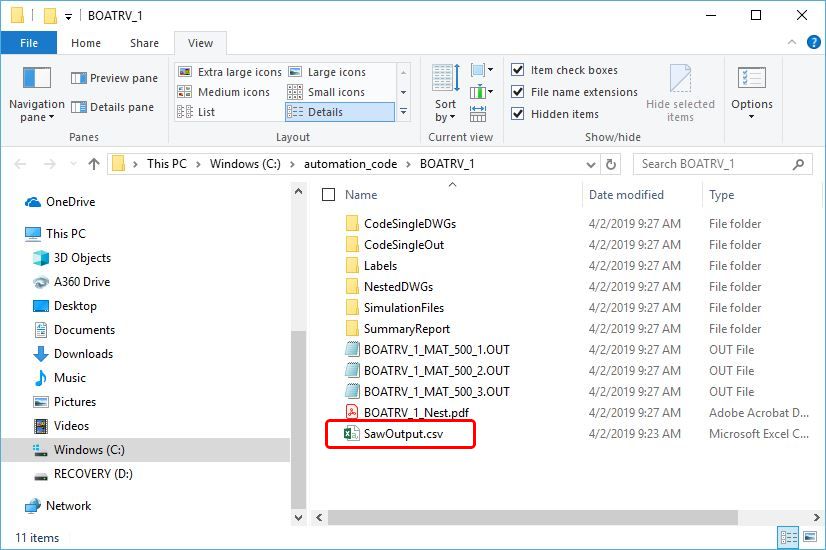
Output to Saw
This option will output a CSV that will include the information needed to feed to a saw optimization software.
The information included in the CSV is as follows:
Column A: Part Name (Part Location)
Column B: Material Description
Column C: Quantity
Column D: Record Description
Column E: Material Code
Column F: XDim
Column G: YDim
Column H: ZDim
Column I: Open
Column J: Open
Column K: Open
Column L: Open
Column M: Part Name without the extension
Column N: Router-CIM Part Number
The CSV file created will be placed in the 'Output' folder from Router-CIM Automation Suite.
Generic Record X Dim
When a Router-CIM macro is used, the X dimension setting can be overridden with this field.
Generic Record Y Dim
When a Router-CIM macro is used, the Y dimension setting can be overridden with this field.
Generic Record Z Dim
When a Router-CIM macro is used, the Z dimension setting can be overridden with this field. Note that the material can be used for the Z value to determine a parts thickness.
Rotate Part
Checking this option will force the part to rotate to the angle set in the Rotate Angle field (to the right). Whether or not the material has part rotation set, this field will override the setting and rotate the part from the default view it was drawn in. This setting has no effect on the material rotation angle and any material related settings will occur during the nesting section of a job run.
Only Pattern Recognition will stop this rotation. If a part is being drilled with Pattern Recognition and has more than 1 hole drilled at a time (in other words a pattern of two or more) then the part will be rotation locked and cannot be rotated on the material.
Rotate Angle
Controls the rotation angle of the part when an override to the rotation angle is needed. See above. Based on AutoCAD angle definitions.
Mirror Part
Checking this option will force the part to be mirrored about the axis specified to the right (Mirror Axis).
The mirroring is done prior to cut and it is entirely possible to have a part mirrored and rotated using the rotate commands within this section.
Pattern Recognition has no effect on mirror since the part will still have the orientation of its holes in the same direction.
Mirror Axis
Controls the direction of the mirror. Available options are Vertical or Horizontal. The Mirror Part box must be checked to turn this option on.
Nest Rotation
This is the default setting for the current part nested on a sheet. You can allow it to rotate based on the material settings or force it to override the material settings and control the rotation angle. The available options are Same as Material, ALL, 0, 0 90, 0 180, 0 90 180. Once this setting is changed, the part rotation will be set to this setting and ignore the material setting defined in the Material Database.
NOTE: It is possible to have this rotation set as well as the Rotate Part box checked and multiple angle rotations will occur.
To scale your parts from inch to metric or metric to inch prior to processing the job, please go to 'Scale Part Geometry in Router-CIM Automation Suite'.
Knowledge Information
It is possible to have certain parts in a job nested and cut on one machine, and single parts (not nested) cut on another machine. These single parts can be secondary operations to a particular part, or just some parts that you wish to cut one at a time on a different machine. These parts cannot be nested. They can use a different knowledge drawing, DOIT file, Post Processor, and different part settings. They all, however, must be set to 'Code as Single Part'.
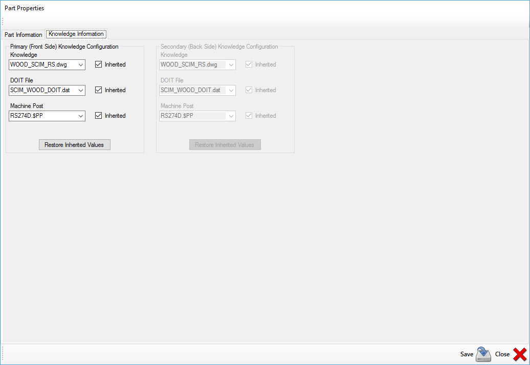
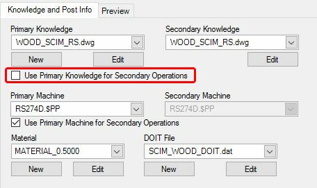
Primary Knowledge Configuration
When a job has parts that are marked as Code as Single Part, the Knowledge Information screen will be available. You can set the Primary Knowledge in this window to run with a different knowledge drawing, DOIT file, and post processor than the other parts that are being cut in the main job.
Secondary Knowledge Configuration
This is only for Router-CIM macros, where the part properties are marked "Has an Associated Backside Macro". The backside macro (same name as the regular macro, with a -b at the end) can be cut with a different knowledge drawing, DOIT file, and post processor than the front side (nested side) of the same macro.
When using this feature, you should uncheck the box marked "Use Primary Knowledge for Secondary Operations" if you need a secondary knowledge drawing, and also the "Use Primary Machine for Secondary Operations" to specify the secondary post processor.
Inherited
Checking the Inherited box in any of these fields will set that particular property to the same settings as the main window is using for the job.