|
|

|

|
|||
|
|
|
|
Note: In order for nesting to know the boundary of the parts, you will need to make sure that you have defined the Outside layer under the 'Layer Lists' tab in the 'Settings' for Router-CIM Automation Suite.
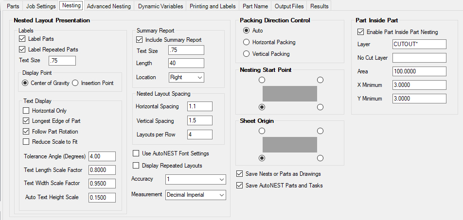
Nested Layout Presentation
This section contains parameters that affect the look of the nested sheet, summaries, and part labels on the nest.
Labels
Label Parts
If you want the parts in the nest labeled, check this option.
This option is ON by default.
Label Repeated Parts
Check this option when you want each part in the nest labeled, even when it is duplicated in the nest pattern.
This option is ON by default.
Text Size
Set the text size (in current units) for the text that appears on the part labels.
Default value is 0.75"
Display Point
Center of Gravity: Place the part label at the center of gravity of the part.
Insertion Point: Place the part label at the insertion point of the part.
Text Display
Horizontal Only: This will place the label unscaled and horizontal only based on the center of gravity of the part only.
Note: The 3 check boxes and the 4 text boxes will be grayed out if this option is selected
Longest Edge of Part: Aligns the label with the longest edge of the part.
Follow Part Rotation: Keeps the label aligned with the part even if the nesting function rotates the part.
Reduce Scale to Fit: Reduces the scale of the text to fit within the part. Text size must be set to 0.0 in order to use this option.
Tolerance Angle (degrees): Degrees in which the text will snap to the nearest X or Y axis.
Text Length Scale Factor: Text Height is computed from the center of gravity of the Part to the nearest edge of the Part’s (smallest) enclosing rectangle. The computed Text Height is reduced by the scale factor (0.8 default). This scale factor can be adjusted depending on the FONT used in the drawing to achieve a visually pleasing result.
Text Width Scale Factor: Text Height is computed from the center of gravity of the Part to the furthest edge of the Part’s (smallest) enclosing rectangle. The computed Text Height is reduced by the scale factor (0.95 default). This scale factor can be adjusted depending on the FONT used in the drawing to achieve a visually pleasing result.
Auto Text Height Scale: When the specified Text Height is “Auto”, each text height is calculated based on the smaller width of the Part’s enclosing rectangle multiply by this factor, 0.15 default.
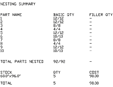
Summary Report
Include Summary Report
The Summary Report is a recap at the end of the last nested sheet that shows how many parts have been nested and the material cost.
Text Size
This setting controls the text size of the summary report.
Location
The location of the Summary Report can be set to either RIGHT, TOP-LEFT, or TOP-RIGHT.
Length
This is the distance between the nested sheets as they are displayed on the screen. This value is in default units.
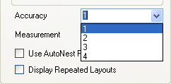
Accuracy
This is a setting for the decimal places that will show for the numbers in the nest summaries. For instance using 1 will show a material as 96.0x60.0. Using more than one will increase the number of decimal locations that are reported. 1-4 are the only possible inputs in the list.
Measurement
The measurement type will be used by the font that displays the units used in the nesting and summaries.
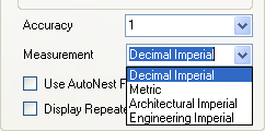
The default setting is Decimal Imperial.
Use AutoNest Font Settings
Checking this box will override the Accuracy and Measurement settings above and use the settings set by the nest program instead.
The default is to leave this box unchecked and use the settings in this menu.
Display Repeated Layouts
Using Display Repeated Layouts will show a nested sheet in the nest drawing for every sheet needed in the job. Typically, if there is a nest that needs to be run more than once, the quantity field will simply show the quantity of that sheet that you need to run, instead of making duplicate nests. So, if you run a job and the nest drawing shows 2 sheets, but there are several programs to run, then you can check the sheet quantity in the nested sheet for how many instances of that sheet are needed.
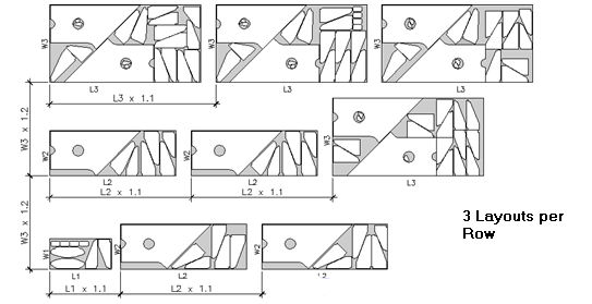
The options in Nested Layout Presentation will allow you to format the result nest drawing so that the nested sheets are easier to see, read and print. You are allowed control over a system of layout that has rows and columns, referred to as Horizontal Spacing, Vertical Spacing, and Layouts per Row.
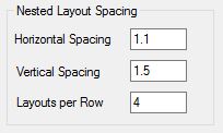
Horizontal Spacing
This is the setting for the horizontal spacing between the nested sheets when repeated horizontally. This would be similar to the spacing between Columns on a spreadsheet.
Vertical Spacing
This is the setting for the vertical spacing between the nested sheets when repeated vertically. This feature would be similar to the spacing between Rows in a spreadsheet.
NOTE: If you are using Automated Two-Side nesting, this value will need to be changed to 2.5 or greater.
Layouts per Row
This is the number of nested sheets in a row to display horizontally. The sheets will continue vertically until all sheets are shown.
Save Nests or Parts as Drawings
Checking this parameter will save a copy of the nest layout drawing or single parts drawings in the job results folder. This is useful to review the nest results for a job.
Save AutoNEST Parts and Tasks
Checking this option will create a folder inside the job results folder containing the AutoNEST parts and task files for the job. This is useful if you want to keep the results folders for backup and need to run the nest later.
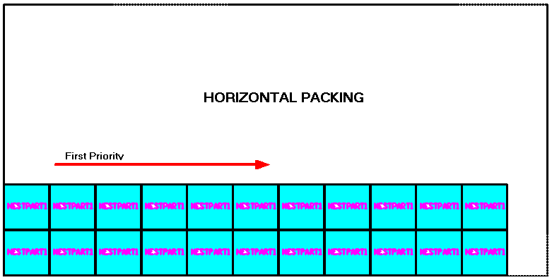
Packing Direction Control
Packing Direction Control is the setting for the method used to place parts on the nested sheet.
Auto
Auto will place parts with no particular preference for Horizontal or Vertical packing, but using the most efficient method to gain yield from the sheet.
Horizontal Packing
Horizontal Packing will favor placing parts across the sheet (in X) before moving up the sheet (in Y).
Vertical Packing
Vertical Packing will favor placing parts moving up the sheet (in Y) before moving across the sheet (in X).
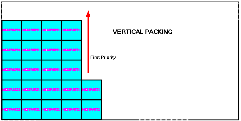
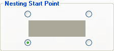
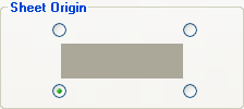
This selection will change the location where nest starts placing the parts.
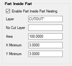
Layer - This is the layer name you want to use for parts to nest inside. For instance with Solid-CIM 3D this would be CUTOUT*. This name MUST be in ALL CAPS.
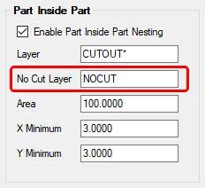
No Cut Layer - This is the layer name you want to use for parts to nest inside when this layer is not actually cut in the nest.
Area - This is the minimum area the geometry must be in order for nest to place parts on it. So, all cutouts that have at least this much area will be considered for PIP nesting.
X Minimum - The minimum size in X for a part to be considered for PIP nesting. For instance if a cutout is bigger than area but it is only 3” long by 40” tall with X Minimum set to 5.00 then this cutout will not get parts nested inside of it because it is not at least 5.00 in the X dimension.
Y Minimum - The minimum size in Y for a part to be considered for PIP nesting. For instance if a cutout is bigger than area but it is only 3” wide by 60” long with Y minimum set to 5.00 then this cutout will not get parts nested inside of it because it is not at least 5.00 in the Y dimension.
If you create a layer on a part that includes _PIP as the suffix, this will trigger the nesting engine to see if it can nest any parts within the geometry that is on that layer as well.