|
|

|

|
|||
|
|
|
|
|
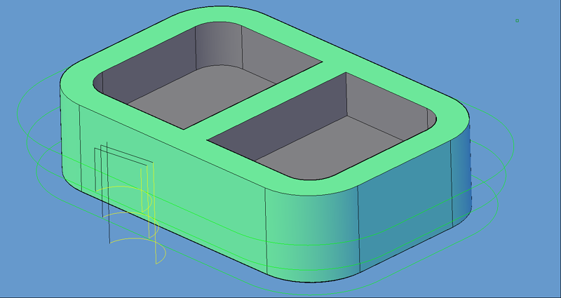
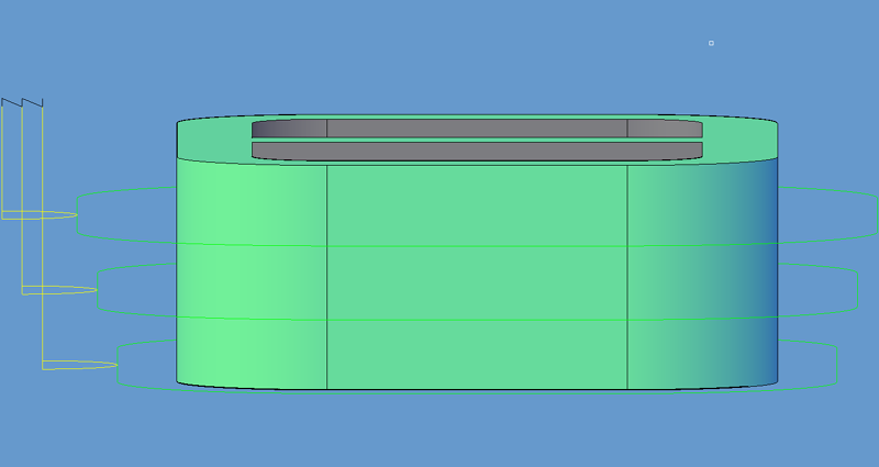
Taper-Plunge cutting is a method of rough and finish cutting with the same tool where the roughing is not only in XY but in Z as well. The cycle will start at the Safety Plane and plunge to the first cut depth and then make a 90° lead-in to make the first pass. The offset of the first pass is typically offset in XY away from the edge of the finished shape. After the first pass takes place, the cutter makes a 90° lead out, retracts the cutter and then moves over to the start of the second cut, which will be closer in XY to the finished edge and lower in Z. It will make the same lead-in move, cut the profile shape and then lead-out and retract, next moving over closer to the finished edge in XY and then plunging in Z down to the next depth. Depending on the set parameters this can occur many times, each time stepping in and down closer to the finished shape of the part, which will be the last pass.
You must use multiple depths per pass to have the cycle parameters create any effect on the tool path. |

Taper-Plunge-Outside cycle parameters.
The following parameters effect the toolpath creation:
Offset Dim
The offset dim is the amount the toolpath is offset from the original geometry or Geoshape.
Normally this is set by Router-CIM depending on a number of features such as the Cutter Compensation setting and the cut cycle itself. For instance if Cutter Comp is set to Yes, then the toolpath will lie directly on top of the Geoshaped geometry with no offset.
You may substitute the parameters here for numeric values to suit you particular cutting needs.
The value set by default (firstxy xycutloc) is a macro setting that allows Router-CIM to handle the offset automatically and will usually not need to be changed.
See the Offset Dim section for more information.
Cut Side
Cut Side is the side of the Geoshape that the toolpath will be created on. For instance Plunge-Outside (Plunge-O) will have the toolpath on the outside of the shape. Valid entries for this field are Outside, Inside, RH (Right Hand) and LH (Left Hand).
See the Cut Side section for more information.
Cut Direction
The direction of the cut can only be clockwise (CW) or counter-clockwise (CCW). This even applies to open shapes where this direction really has no meaningful relationship to the geometry selected. Any closed shapes should have the direction set accordingly and any open shapes should be set to CCW as all shapes in AutoCAD and Router-CIM are CCW by default.
See the Cut Direction section for more information.
Round Corners
If set to Yes, this option will round sharp corners with a radius of the value stored in the task *cutfil*. The default is 0.01 radius. This option will insert a fillet in all corners, so if you have an inside cut you will most likely cause an error when the tool tries to fit into that radius. If you have inside and outside cuts on the same shape and need to fillet the corners, use the AutoCAD Fillet command, then Geoshape and Cut the shape.
See the Round Corners section for more information.
Lead In
This field defines the lead-In block name. There are several available, but only some cycles will respond to the change of the Lead-In edits. By default this cycle will usually not have the lead-in or lead-out changed as the defaults will accommodate multiple depths per pass and cutting on any plane.
See the Lead-In section for more information.
Lead Out
This field defines the lead-Out block name. There are several available, but only some cycles will respond to the change of the Lead-Out edits. By default this cycle will usually not have the lead-in or lead-out changed as the defaults will accommodate multiple depths per pass and cutting on any plane.
See the Lead-Out section for more information.
Lead Size
Use Lead Size to change the length of the leads. This field will affect both lead-in and lead-out if you put just one number in this field. You can put two numbers in this field, separated by a space, and the first number will affect the lead-in and the second will affect the lead out.
See the Lead-Size section for more information.
Lead Angle
Use Lead Angle to change the angle of the lead-in and lead-out. This field also will affect both lead-in and lead-out angles if you put just one number in the field. You can put two numbers in this field, separated by a space. The first number will affect the lead-in angle and the second will affect the lead-out angle.
See the Lead Angle section for more information.
This parameters specifies how far each pass is from one another in the XY plane. Even though the cuts can step in the Z axis, they have an XY step over amount as this would control the amount of material removed by the tool on each pass.
The Z axis step is controlled by the Depth per Pass and Taper Angle.
Finish is the offset amount from the edge of the part where the finish pass is placed, in the XY plane. Typically for a finish cut this would be the radius of the tool, for a roughing cut it would be the tool radius plus the amount of material you desire to leave for the finish cutter to remove.
The angle in degrees to try and step each cut as they get closer or further away from the part. This would be the angle between the passes in Z.
Lead Feed
This sets lead-in and lead-out feed rates. The default is 0.5, Router-CIM's standard 50% feedrate for lead-in and lead-out. Whatever number you set this variable to is a percentage of max feedrate set in the Control Panel. Setting the number to a value greater than 1.0 will give you an exact feedrate.
See the Lead Feed section for more information.
Safety Plane
The safety plane is the location in the Z axis where the tool can retract to between cuts.
This should always be a value that places the cutter above the part to be cut as each tool change, or index move between cuts is going to start from this point.
Placing an asterisk ( * ) before the number specifies that this value is an absolute point above the part, where leaving this out determines the point to be incremental.
See the Safety Plane section for more information.
Depth Per Pass
This field allows multiple depths of Cut in a single tool path. By setting this number to a value less than the Total Depth of the Cut, you will have multiple passes in the material.
For example, if you have 1" thick material and need to take three passes to Cut through, you would set the Depth/Pass field at .4 (any number between .35 and .5 is valid) and the Total Depth at -1.0. The code generated will produce the first pass at -.4, the second at -.8 and the third pass at -1.0.
In most of the standard Router-CIM cycles the tool paths will ramp down between the Cuts.
Total Cut Depth
The Total Cut Depth is the depth you wish to Cut to based on the top of the geometry, regardless of the number of passes made. Router-CIM uses this number to calculate the Z axis moves for the Total Depth to Cut into the material. If the Depth Per Pass field has a number smaller than this, Router-CIM calculates the number of passes necessary to reach this depth.
See the Total Cut Depth section for more information and the options available.
Feedrate
This field specifies the cutting maximum Feedrate in either inches per minute or millimeters per minute, depending on the mode you are programming in. See the chapter on Advanced Settings for information on how to program variable feed rates.
Spindle Speed
This field sets the spindle speed in rpm's (revolutions per minute). This is a modal field to many machine tools, so if you do not change this field for each Cut with the same spindle, you may only see the output for this setting once although you have made more than one Cut with the same spindle.
Values placed here will be output in the cut cycle before the tool enters the material, typically at the height of the Safety Plane once the tool length compensation is set.
Values placed here will be output in the cut cycle after the tool has retracted from the cut, typically at the height of the Safety Plane after the cut is finished.
A numeric value to use for the tool path created to allow the Sequencer to place cuts in a specific order when the code is created.
Overlap Amt
Overlap is the movement of the cutter past the starting point of the cut. By default the Overlap amount is equal to the diameter of the tool. You are able to specify a larger or smaller amount for this by placing a value in this field. For instance, if you are using a 0.5" router bit, the Overlap distance is 0.5". If you put 1.0" in the Overlap Amt. field then the Overlap will be 1.0". This is typically done to reduce any witness mark in the material left by the tool on the lead-in maneuver.
See the Overlap Amt section for more information.
**Changing values in the cycle parameters may yield unexpected results with some settings or on some geometry. Examine the toolpath and NC Code carefully before running your machine tool if you change these default settings.