|
|

|

|
|||
|
|
|
|
This field defines the lead-Out block name. There are several available, but only some cycles will respond to the change of the Lead-Out edits.
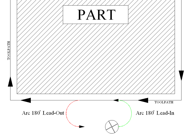
Only certain cycles are valid for setting the Lead-In or Lead-Out:
Plunge-Outside Line Leads
Center-Line Cut
Right Hand/Left Hand Cut
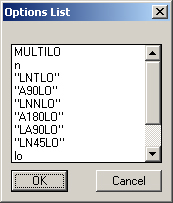
The options selected from the Options Box by default are:
MULTILO
Multilo is the default lead type for some cycles where there are multiple depth per pass, and Router-CIM must figure out how to move each cut down (usually ramping) between passes.
This is typically not a user selectable option.
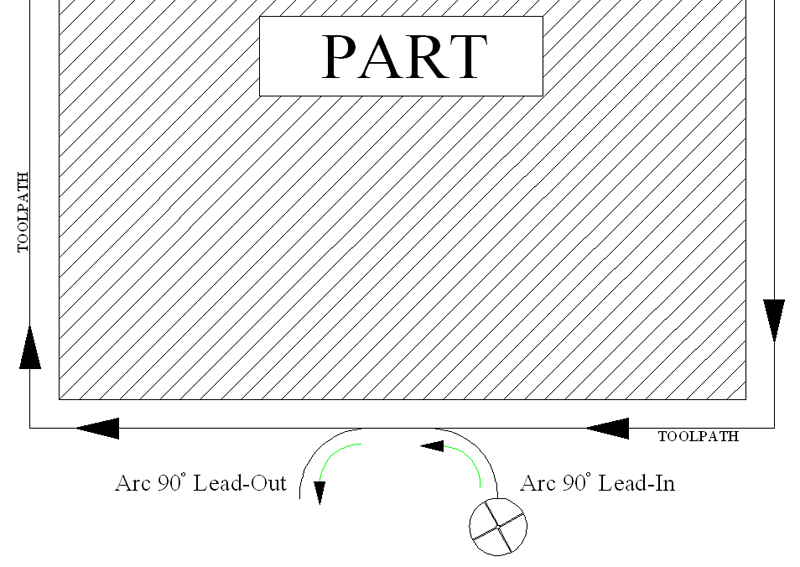
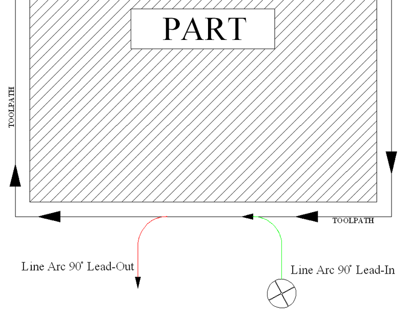
LA90LO
Line and Arc 90° Lead Out. There will be a short line, then a 90° arc, starting tangent to the end of the cut.
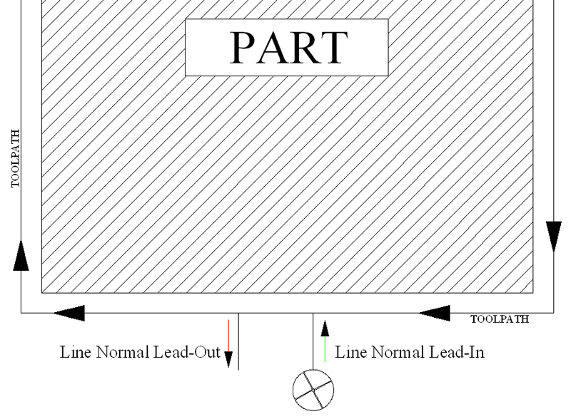
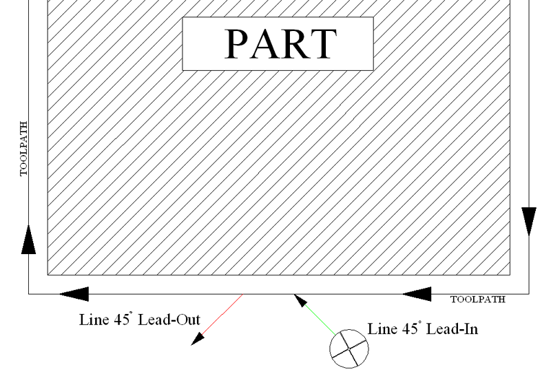
LN-45LO
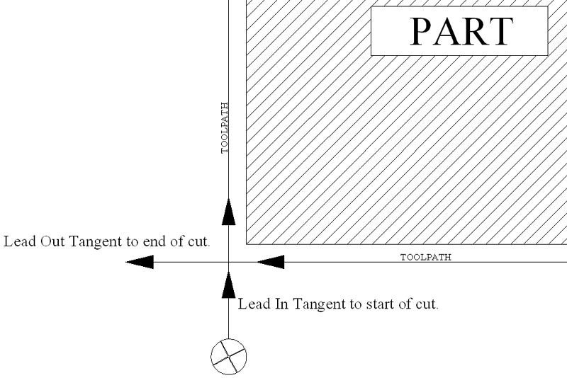
Line 45° Lead Out. This method generates a line at a 45° angle to the end of the cut.
lo
This is a Router-CIM macro that will generate a line lead out, in various configurations depending on the cut settings. This is not a user selectable option.
Additional Leads can be made in the /Router-CIM/Ncdwgs/(Knowledge Drawing based on the name of your postprocessor i.e. Mach1s, Mach2s, etc.) drawing by drawing a polyline on layer NC_LEADS beginning at 0,0 for a lead-out. Make a block from the polyline with a 0,0 insertion point.
After the block is created you should erase the lead from the drawing and change the current layer back to Layer 0.
Save the drawing back to your /Router-CIM/Ncdwgs directory.
The next time you want to use the new lead, choose the Plunge Outside line leads cycle and enter the block name of the lead-out you chose to create, in the appropriate field in the Control Panel.