|
|

|

|
|||
|
|
|
|
|
This cycle allows for a rough cut and finish cut on the inside of a shape according to dimensions that you specify in cycle parameters. The cycles creates multiple, offset toolpaths from the inside of the shape towards the finished edge, with specified dimensions for the amount of the first pass, last pass, and cut spacing. You also specify how far away from the finished edge the finish pass is created. The tool will start at the Safety Plane, ramp down to the depth specified in Total Cut Depth or Depth per Pass and then make a straight lead in to the location of the first pass set by the Max Offset. The cutter will make the first pass, then step in towards the finished edge according to the XY Step amount and make another pass until it reaches the offset for the Last Offset. On the Last Offset, the tool will move back and over to a point where it can make a 90° lead-in arc, then cut the finish pass back to the start point, overlap the start point by the tool diameter and make a 90° lead-out arc before retracting back up to the Safety Plane. |
One of the main differences between the Multi-Pass Inside and Multi-Pass Outside is that the Inside cycle will make a contour following ramp-in for the first pass. This means that this cycle can be used to remove material from an area inside a shape without a rougher tool having to remove any material first.

Multi-Pass Inside cycle parameters
This cycle will only offset shapes that can be offset in AutoCAD, and if the AutoCAD offset command fails, so will this cutting cycle. There is no provision for leaving 'islands' or separate areas that are uncut in the shape. This is not a pocketing cycle. There are some cut properties unique to this cycle, each of them is explained below.
The following parameters effect the toolpath creation:
Offset Dim
The offset dim is the amount the toolpath is offset from the original geometry or Geoshape.
Normally this is set by Router-CIM depending on a number of features such as the Cutter Compensation setting and the cut cycle itself. For instance if Cutter Comp is set to Yes, then the toolpath will lie directly on top of the Geoshaped geometry with no offset.
You may substitute the parameters here for numeric values to suit you particular cutting needs.
The value set by default (firstxy xycutloc) is a macro setting that allows Router-CIM to handle the offset automatically and will usually not need to be changed.
See the Offset Dim section for more information.
Cut Side
Cut Side is the side of the Geoshape that the toolpath will be created on. For instance Plunge-Outside (Plunge-O) will have the toolpath on the outside of the shape. Valid entries for this field are Outside, Inside, RH (Right Hand) and LH (Left Hand).
See the Cut Side section for more information.
Cut Direction
The direction of the cut can only be clockwise (CW) or counter-clockwise (CCW). This even applies to open shapes where this direction really has no meaningful relationship to the geometry selected. Any closed shapes should have the direction set accordingly and any open shapes should be set to CCW as all shapes in AutoCAD and Router-CIM are CCW by default.
See the Cut Direction section for more information.
Round Corners
If set to Yes, this option will round sharp corners with a radius of the value stored in the task *cutfil*. The default is 0.01 radius. This option will insert a fillet in all corners, so if you have an inside cut you will most likely cause an error when the tool tries to fit into that radius. If you have inside and outside cuts on the same shape and need to fillet the corners, use the AutoCAD Fillet command, then Geoshape and Cut the shape.
See the Round Corners section for more information.
Lead In
This field defines the lead-In block name. There are several available, but only some cycles will respond to the change of the Lead-In edits. By default this cycle will usually not have the lead-in or lead-out changed as the defaults will accommodate multiple depths per pass and cutting on any plane.
See the Lead-In section for more information.
Lead Out
This field defines the lead-Out block name. There are several available, but only some cycles will respond to the change of the Lead-Out edits. By default this cycle will usually not have the lead-in or lead-out changed as the defaults will accommodate multiple depths per pass and cutting on any plane.
See the Lead-Out section for more information.
Lead Size
Use Lead Size to change the length of the leads. This field will affect both lead-in and lead-out if you put just one number in this field. You can put two numbers in this field, separated by a space, and the first number will affect the lead-in and the second will affect the lead out.
See the Lead-Size section for more information.
Lead Angle
Use Lead Angle to change the angle of the lead-in and lead-out. This field also will affect both lead-in and lead-out angles if you put just one number in the field. You can put two numbers in this field, separated by a space. The first number will affect the lead-in angle and the second will affect the lead-out angle.
See the Lead Angle section for more information.
Max Offset
Max Offset is the distance from the start point to the start of the first pass on the cut. If the cut cycle is Multi-Pass Inside, then the Max Offset will be to the inside of the shape by the specified amount. If the cycle is Multi-Pass Outside, then the Max Offset will be from the start point to the outside of the shape by the Max Offset amount. This is only the distance for the first cut. All subsequent cuts will be determined by either XY Step or Last Offset.
XY Step Size
The XY Step is the distance between each tool path from the first to the last (excluding the finish pass) on the Multi-Pass Inside and Multi-Pass Outside cycles.
You can specify the distance as a numeric value, or you can make a task to calculate a step over amount and place the task name in the XY Step field. An example of a task is TW80, which looks at the tool diameter field and then places an amount equal to 80% of that value in this location.
Last Offset
The Last Offset is the distance from the finish pass to the edge of the shape being cut. This can be any numeric value, but if it exceeds the XY Step value, the cutter will not contact the part on the finish pass. Typically this is set to the radius of the tool in a rough-cut, finish-cut scenario. You can leave some material on the part if you want to clean up the part with a finish cutter.
Lead Feed
This sets lead-in and lead-out feed rates. The default is 0.5, Router-CIM's standard 50% feedrate for lead-in and lead-out. Whatever number you set this variable to is a percentage of max feedrate set in the Control Panel. Setting the number to a value greater than 1.0 will give you an exact feedrate.
See the Lead Feed section for more information.
Safety Plane
The safety plane is the location in the Z axis where the tool can retract to between cuts.
This should always be a value that places the cutter above the part to be cut as each tool change, or index move between cuts is going to start from this point.
Placing an asterisk ( * ) before the number specifies that this value is an absolute point above the part, where leaving this out determines the point to be incremental.
See the Safety Plane section for more information.
Depth Per Pass
This field allows multiple depths of Cut in a single tool path. By setting this number to a value less than the Total Depth of the Cut, you will have multiple passes in the material.
For example, if you have 1" thick material and need to take three passes to Cut through, you would set the Depth/Pass field at .4 (any number between .35 and .5 is valid) and the Total Depth at -1.0. The code generated will produce the first pass at -.4, the second at -.8 and the third pass at -1.0.
In most of the standard Router-CIM cycles the tool paths will ramp down between the Cuts.
Total Cut Depth
The Total Cut Depth is the depth you wish to Cut to based on the top of the geometry, regardless of the number of passes made. Router-CIM uses this number to calculate the Z axis moves for the Total Depth to Cut into the material. If the Depth Per Pass field has a number smaller than this, Router-CIM calculates the number of passes necessary to reach this depth.
See the Total Cut Depth section for more information and the options available.
Feedrate
This field specifies the cutting maximum Feedrate in either inches per minute or millimeters per minute, depending on the mode you are programming in. See the chapter on Advanced Settings for information on how to program variable feed rates.
Spindle Speed
This field sets the spindle speed in rpm's (revolutions per minute). This is a modal field to many machine tools, so if you do not change this field for each Cut with the same spindle, you may only see the output for this setting once although you have made more than one Cut with the same spindle.
Values placed here will be output in the cut cycle before the tool enters the material, typically at the height of the Safety Plane once the tool length compensation is set.
Values placed here will be output in the cut cycle after the tool has retracted from the cut, typically at the height of the Safety Plane after the cut is finished.
A numeric value to use for the tool path created to allow the Sequencer to place cuts in a specific order when the code is created.
Overlap Amt
Overlap is the movement of the cutter past the starting point of the cut. By default the Overlap amount is equal to the diameter of the tool. You are able to specify a larger or smaller amount for this by placing a value in this field. For instance, if you are using a 0.5" router bit, the Overlap distance is 0.5". If you put 1.0" in the Overlap Amt. field then the Overlap will be 1.0". This is typically done to reduce any witness mark in the material left by the tool on the lead-in maneuver.
See the Overlap Amt section for more information.
Additional notes for Multi-Pass Inside:
If you are using this cycle to remove all of the material from the inside of a shape, then there are two things to consider.
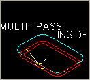
First, the shape you are cutting must be a regular shape that the AutoCAD offset command can work on to make regular offsets that will clean out the entire area. If the AutoCAD offset command fails to be able to make enough offsets, then this cut cycle will not make the proper tool paths. Shown below is an example of how an irregular shape could fail the offset. For these types of shapes, the Pocketing cycles are appropriate.

Multi-Pass Inside cycle on irregular shape.
Second, if you have a regular shape (rectangle, circle, etc.) and you must remove all the material inside the shape with the Multi-Pass Inside cycle, you will have to do some calculations for the Max Offset. Since Max Offset is the offset distance from the edge of the finished shape to the start of the first cut, you will have to calculate the distance of that first offset tool path.
There are some simple formulas to use for regular shapes.
To calculate how far to make the Max offset on a circular shape, you can take the Radius of the circle, which would get you to the exact center, then subtract the tool radius to get an offset from the center (otherwise the tool would move down to the center, kind of like a drill with no other motion to make), then add how much of an overlap you want on the first pass.
So, in example to cut a 5" diameter circle, with a .5" Router-Bit, you would start with a Max offset of about 2.35. That is using an overlap of .10 on the first pass.
Diameter / 2 = Circle Radius Tool Diameter / 2 = Tool Radius Overlap = .10 Circle Radius - Tool Radius + Overlap = Max Offset |
5.0 / 2 = 2.5 0.5 / 2 = .25 2.5 - .25 = 2.25 2.25 + .10 = 2.35 |
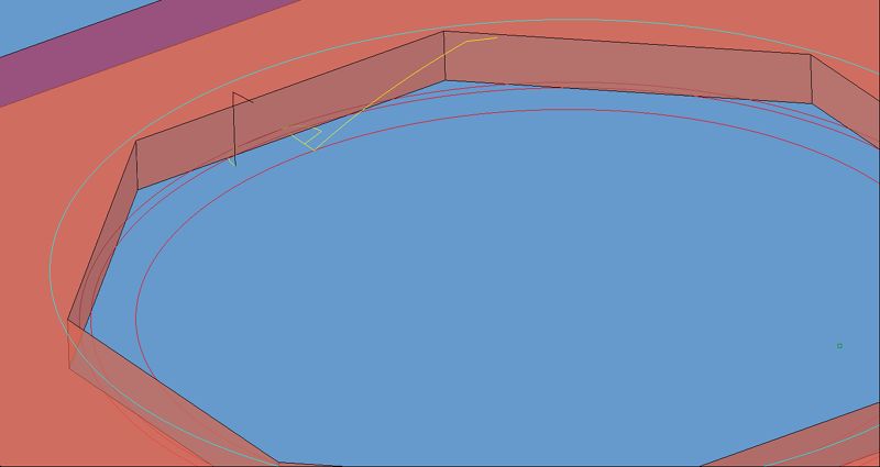
The result of using the Max Offset of 2.15, an XY Step of .25 and a Last Offset of .25 would look like this:

Multi-Pass Inside on circular shape.
To calculate the distance of the Max Offset on a rectangular shape, you can take the width of the narrow side divided by 2 (to get to the middle of the shape) then subtract the tool radius and add the overlap amount you want on the first pass.
So, in example, to cut a 10" x 3" rectangular shape, you would need a Max Offset of about 1.35, using an overlap of .10 on the first pass.
Width of narrowest side / 2 Tool Diameter / 2 Overlap on first pass = .10 Width / 2 - Tool Radius + Overlap = Max Offset |
3.0 / 2 = 1.5 0.5 / 2 = .25 1.5 - .25 = 1.25 1.25 + .10 = 1.35 |
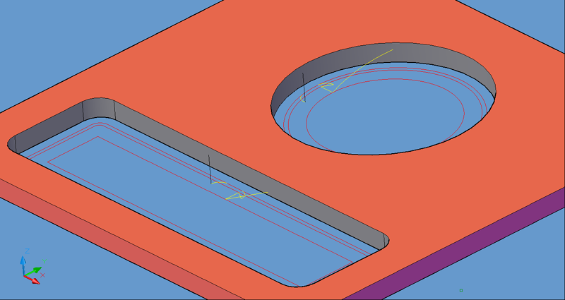
The result of using the Max Offset of 1.35, an XY Step of .25 and a Last Offset of .25 would look like this:

Multi-Pass Inside on a rectangular shape.
The reason for using a smaller first offset amount than the XY Step size or Last offset is only because you need to remove the overlap on the starting pass, each step after that will remove the overlap from the pass before it, so a smaller amount was used. Feel free to use any amount that is just short of the tool radius, as some tools are slightly undersized even when new, and worse as they wear.
**Changing values in the cycle parameters may yield unexpected results with some settings or on some geometry. Examine the toolpath and NC Code carefully before running your machine tool if you change these default settings.