|
|

|

|
|||
|
|
|
|
|
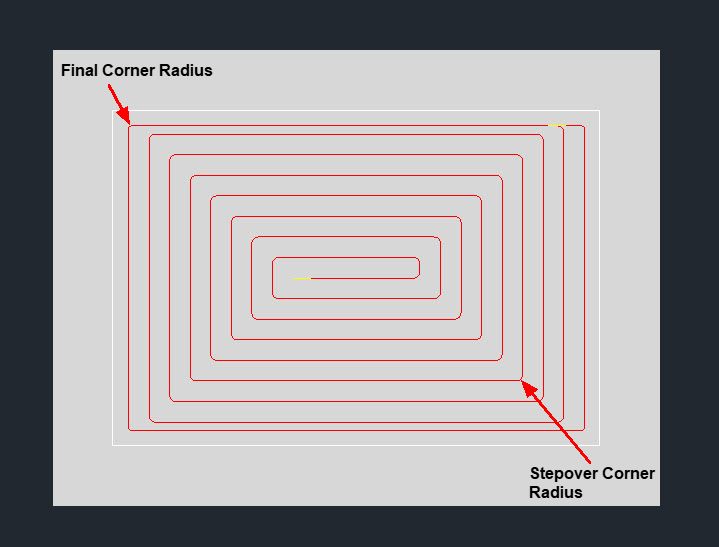
The Rectangular Fast Pocket cycle gives you the ability to create a radius in the corner of the pocket to prevent the machine from coming to a stop when making a corner move. The Rectangular Fast Pocket cycle also allows for a unique corner radius for the final corners to make sure you are getting the corners you would expect. Take advantage of up to a 75% step over in the Rectangular Fast Pocket cycle.
Note: This cycle will only work with a rectangular shape. |


The following parameters effect the toolpath creation:
Offset Dim
The offset dim is the amount the toolpath is offset from the original geometry or Geoshape.
Normally this is set by Router-CIM depending on a number of features such as the Cutter Compensation setting and the cut cycle itself. For instance if Cutter Comp is set to Yes, then the toolpath will lie directly on top of the Geoshaped geometry with no offset.
You may substitute the parameters here for numeric values to suit you particular cutting needs.
The value set by default (0.0) is a macro setting that allows Router-CIM to handle the offset automatically and will usually not need to be changed.
See the Offset Dim section for more information.
Cut Side
Cut Side is the side of the Geoshape that the toolpath will be created on. Valid entries for this field are Outside, Inside, RH (Right Hand) and LH (Left Hand).
See the Cut Side section for more information.
Cut Direction
The direction of the cut can only be clockwise (CW) or counter-clockwise (CCW). This even applies to open shapes where this direction really has no meaningful relationship to the geometry selected. Any closed shapes should have the direction set accordingly and any open shapes should be set to CCW as all shapes in AutoCAD and Router-CIM are CCW by default.
See the Cut Direction section for more information.
Round Corners
If set to Yes, this option will round sharp corners with a radius of the value stored in the task *cutfil*. The default is 0.01 radius (in inch mode). This option will insert a fillet in all corners, so if you have an inside cut you will most likely cause an error when the tool tries to fit into that radius. If you have inside and outside cuts on the same shape and need to fillet the corners, use the AutoCAD Fillet command, then Geoshape and Cut the shape.
See the Round Corners section for more information.
Lead In
This field defines the lead-In block name. There are several available, but only some cycles will respond to the change of the Lead-In edits. By default this cycle will usually not have the lead-in or lead-out changed as the defaults will accommodate multiple depths per pass and cutting on any plane.
See the Lead-In section for more information.
Lead Out
This field defines the lead-Out block name. There are several available, but only some cycles will respond to the change of the Lead-Out edits. By default this cycle will usually not have the lead-in or lead-out changed as the defaults will accommodate multiple depths per pass and cutting on any plane.
See the Lead-Out section for more information.
Lead Size
Use Lead Size to change the length of the leads. This field will affect both lead-in and lead-out if you put just one number in this field. You can put two numbers in this field, separated by a space, and the first number will affect the lead-in and the second will affect the lead out.
See the Lead-Size section for more information.
Lead Ratio
Lead Ratio determines the angle of the ramp in Z during the lead in and lead out. You can specify the Lead Ratio as a number that reflects the percentage of the angle from its default. That means that if you want a lead that is twice the normal ramp length (shallower angle) enter 2. If you want a lead that is steeper than the default, enter .5.
See the Lead Ratio section for more information.
Lead Feed
This sets lead-in and lead-out feed rates. The default is 0.5, Router-CIM's standard 50% feedrate for lead-in and lead-out.
Setting a number between 0 and 1.0 will give you a percentage of the max feedrate (for instance 0.4 would be 40%).
Setting the number to a value greater than 1.0 will give you an exact feedrate. For instance 250. would generate F250. in the code.
See the Lead Feed section for more information.
XY Stock Allowance
Placing a value in this parameter will offset the tool path to leave material for a finish pass. For instance, placing .125 in the XY Stock Allowance and cutting a 6.4 x 4.0 shape will actually leave a part that is 6.25 x 4.25, by adding .125 to the offset of the tool path all the way around the part.
See XY Stock Allowance for more information.
Z Stock Allowance
Placing a value in Z Stock Allowance will change the Total Cut Depth by the number entered. You can use this if you want to leave a small amount of material on the bottom of a part, or if you intentionally want to overcut a part to be sure it is cut all the way through.
Entering a positive number will move the tool path UP in Z, leaving more material for a finish pass.
Entering a negative number will move the tool path DOWN in Z, past the normal Total Cut Depth.
See Z Stock Allowance for more information.
The value entered here will be added to Finish Pass above to provide material left for a clean up pass on the pocket with a separate tool.
This value is the percentage of the tool diameter in decimal between each pass of the tool in the pocket. This needs to be a real number between 0.05 and 0.75.
The value entered here will be become an arc move for each corner that the pocketing pass does.
The value entered here will be become an arc move for each corner on the final pass of the pocket.
Final Overlap amount is the movement of the cutter past the starting point of the cut. By default the overlap amount is equal to the radius of the tool (*tr*). You are able to specify a larger or smaller amount for this by placing a value in this field. For instance, if you are using a 0.5" router bit, the overlap distance is 0.25". If you put 1.0" in the overlap Amt. field then the overlap will be 1.0". This is typically done to reduce any witness mark in the material left by the tool on the lead-in maneuver.
See the Overlap Amt section for more information.
**Changing values in the cycle parameters may yield unexpected results with some settings or on some geometry. Examine the toolpath and NC Code carefully before running your machine tool if you change these default settings.