|
|

|

|
|||
|
|
|
|
At times you may like to nest a series of tasks overnight or during a break. This facility is provided via the BatchNesting command. But to view the already nested layouts, select the ViewNEST command if you are working in AutoCAD. In Nest Manager, just open each of the nested results saved in .DXF files from the ‘Task Directory’ using a CAD or a DXF Viewer.
If the “Include Sub-Folders” check-box is marked, BatchNesting is able to find and nest Tasks (.JOB) residing on sub-folders.
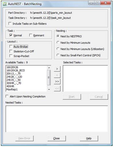
Select the BatchNesting command from the icon or pulldown menu. The following dialog box will appear:
Parts Directory |
Display the default part directory as set in the Sysdata. |
||
Task Directory |
Display the default task directory as set in the Sysdata. |
||
Include Tasks on Sub-Folders |
When this check-box is marked, all the task files residing on all the subfolders of the specified Task Directory will be displayed onto the “Available Tasks” list box. For example : Parts Directory : E:\TestData\AutoNEST-QA-Testing\Others Task Directory : E:\TestData\AutoNEST-QA-Testing\Others
All task files (.JOB) residing on subfolders, to a maximum of two levels from ….\Others will be displayed for selection.
|
||
Task |
There are 2 check-boxes:- |
||
q Normal q Remnant |
|
|
|
‘Normal’ tasks refer to all the task files (*.job) created by the user. ‘Remnant’ tasks refer to tasks files (*.job) with the reserved suffix, ‘_$REM’ . For example : sample_$REM.job. These tasks are automatically created if the “Save Remnant” check-box in the Nesting Options of TaskEdit is marked. For more details, refer to TaskEdit. |
|||
Nesting |
From version 9.12.2 or higher, there are 4 nesting engines :- •Nest by NESTPRO •Nest by Minimum Layouts •Nest by Minimum Layouts (Utilization) •Nest by Small-Part Control (SPCN) You can select the nesting engine of your choice. Detailed explanation of each engine is explained in Chapter 5.5 Nesting.
The default is NESTPRO which is best suited for most jobs. However when the parts’quantities are high, it is recommended you use “Minimum Layouts (Utilization)” nesting engine. This engine is designed to optimize the utilization of the stocks as well as to achieve a high repeatability of the layouts, thus minimizing the number of different nested layouts. “Minimum Layouts” engine is only suitable when the stock materials are inexpensive and the objective is the maximize the repeatability of the nested layouts or cutting plan. “SPCN” is only suitable for cutting machines with un-uniform suction where certain areas have weak suction. Therefore small-parts should not be nested over such weak suction area(s). This new nesting engine will ensure small-parts are nested within the designated “Small-part Zone”. |
Layout |
There are three checkboxes :- q Auto-Bridge q Skeleton-Cut-Off q Scrap-Pocket Mark the ‘Auto-Bridge’ checkbox if you wish to include bridging into the nested layouts. Similarly mark the ‘Skeleton-Cut-Off’ or “Scrap-Pocket” checkbox if you wish to include skeleton-cut-off’s or scrap-pockets into the nested layouts. AutoBridge, Skeleton-Cut-Off and Scrap-Pocket will follow the specifications as defined in TaskEdit. |
Available Tasks |
Display a list of tasks ( .JOB ) files found in the task directory. You can select one or more files to be nested by highlighting the file names and then click the
|
Selected Tasks |
Display a list of task files selected to be nested. Click the
You can click the |
Alert Upon Nesting Completion |
When this check-box is marked and when the batch nesting process is completed, BatchNesting will play the Windows default sound three times to alert the user (provided the speakers are correctly connected to the computer and turned-on). |
Nested Tasks |
Display a list of successfully nested task files. Click the
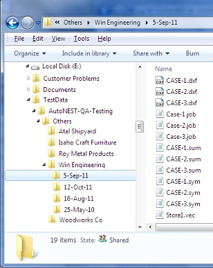
Internally, once a task has been successfully nested, output files will be created. These files have the same name as the task but different file extensions as shown below. Example : Task name is SAMPLE Output Files: SAMPLE.SYM SAMPLE.SUM SAMPLE.XLS or .XLSXSAMPLE_SYM.XMLSAMPLE_SYM.XMLThe .SYM file contains the results of the nesting in terms of each part and its location in the layout.
The .SUM file contains the nesting summary report in TEXT format.
The .XLS or .XLSX file contains the nesting summary in Excel format.
The two .XML files contain the same information as .SYM and .SUM but written in extensible markup language (XML). |
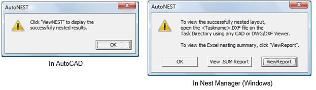
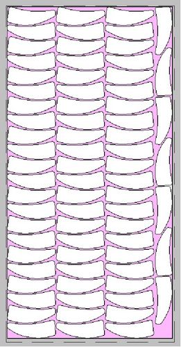
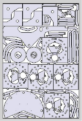
In AutoCAD, when the nesting has completed, you may use the ViewNEST command to view the nested results or open each of the nested layout (DXF files) from the Task directory.
In Nest Manager, upon the completion of the nesting, you can open the nested layout (DXF file) from the Task directory using a CAD or a DXF Viewer. To view the report of each of the nested results, click the “View .SUM Report” button or the “View Report” button to view the Excel report.
Notes on Nested Layouts
1.The display of the nested results will be determined by the settings in “Nested Layout – Presentation” and “Nested Layout – Layer / Color Setting” of Sysdata.
2.You can choose to display the parts in their original layers /colors by selecting “DXF” or “DWG” in “File Format” of Sysdata.
3.Conversely you can choose to display the parts in “VEC” File Format where you can determine the layers /colors of:
•External or outer profile of the Part
•Internal or inner profile of the Part