|
|

|

|
|||
|
|
|
|
Sysdata is an important command to set the working environment for running AutoNEST. Before you begin to work with any of the other AutoNEST commands, it is recommended that the Sysdata command be activated to set the working environment.
Select the Sysdata command and the following dialog box will be displayed.
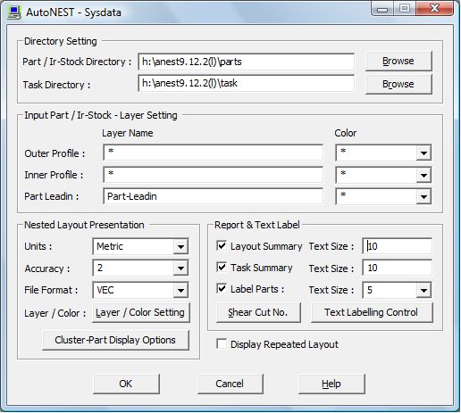
Directory Setting |
|
Parts/ IR-Stock Directory |
To type in or click the |
Task Directory |
To type in or click the |
Input Part /IR-stock – Layer Setting |
|
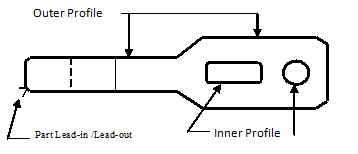
Outer Profile Inner ProfilePart Leadin |
These are the layer, color and the parts’ leadin/leadout “FILTER” settings that you can specify for the following commands. •SavePart & SaveIrStock •ConvertPart & ConvertIrStock
These settings are especially helpful if the parts that you are saving or converting contain marking lines that touch or intersect the external /internal profiles of the shapes.
By specifying the layer/ color/ part leadin filters, you will help the above commands to differentiate profiles that are crucial to nesting (outer and inner profiles of the part) against those that are not (markings or folding lines).
You can specify more than ONE colors in the “Color” field by entering for example “1,3” for colors 1 and 3 (separated by a comma) |
Nested Layout Presentation |
|
Units |
The units setting of inputs and outputs. There are 4 choices to choose from:
Metric Architectural Imperial (1’ 3-1/4”) Decimal Imperial (15.25”) Engineering Imperial (1’ 3.25”) |
Accuracy |
The number of decimal places or the number of digits to the right of the decimal point (0 to 4). If the units chosen above is Imperial, the denominator of the fractions or the accuracy will be expressed as follows:
1 for full integers, no fractions 2 for 1/2" (half) 4 for 1/4" (quarter) 8 for 1/8" (eighth) 16 for 1/16’ (sixteenth) |
File Format |
This option decides which part file format is to be used when generating graphical nested layout on screen. Three choices are available : DWG VEC DXF
If you have chosen VEC format, please note the “Nested Layout – Layer Settings” (click the “Layer Setting” button) to define the layers and colors of the nested layout.
If you have chosen DXF or DWG format, the nested layouts will display the layers/ colors of your parts as they were originally created. |
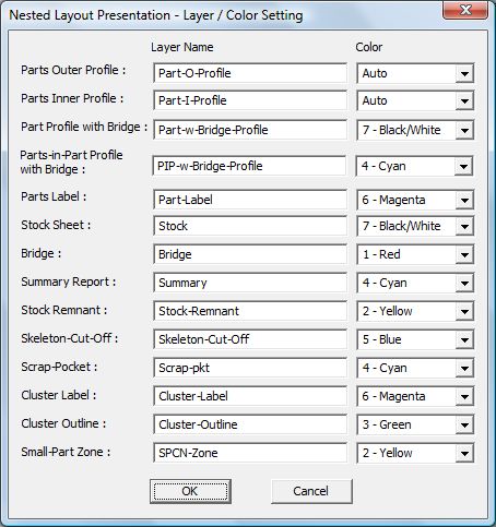
Layer / Color |
The following dialog box will appear when you click this button |
|
|
|
User can define the layer and color for Part Labels, Stock Sheet and Summary reports.
PARTS If the Sysdata “File Format” is VEC, the Parts displayed on the nested layout will follow the layer and color settings here. If DWG or DXF “File Format” are chosen, the Parts’ layer and color settings will be exactly the same as they were originally saved.
See diagram below for explanation of each of the names. |
|
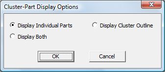
Display Individual Parts If this option is chosen, the individual Parts of each Cluster-part will be displayed. This is the default option.
Display Both If this option is chosen, the individual Parts and the outline of each Cluster-part will be displayed.
Display Cluster Outline If this option is chosen, only the outline of the Cluster-part is displayed. |
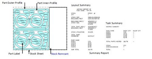
Layout Summary Task Summary
|
Layout Summary – report on the nested results of a particular nested layout. By default this report is displayed at the lower right corner of each nested layout. Task Summary – report summary on the nested results of a Task (.job). By default this report is displayed next to the Layout Summary of the last nested layout. Mark the relevant check-boxes if you wish to display the reports and set the Text Size of the Reports when displayed on screen. See the Illustrations on top of Page 5-4. You can change the default position of these reports in ANEST.SET @LAYOUT.
To change the layer/color of the Reports, click the “Layer/ Color Setting” button |
Text Size |
Text Size of the Reports as displayed on screen. |
Label Parts
|
Mark this check-box if you wish to display Part Labels and set the Text size of the Part label when displayed on screen. To change the layer/ color of the Part labels, click the “Layer/ Color Setting” button. |
Text Size |
Text size of the part label when displayed on screen. “Auto” means the text size displayed will always be proportional to the size of the part. |
Label Repeated Parts |
Mark this check-box if you wish to add a part Label on each and every part on the nested layout. When this check-box is un-marked, when there are say 10 parts of the same name nested, only ONE of the 10 is being labeled. |
Layout Summary |
Layout Summary – report on the nested results of a particular nested layout. By default this report is displayed at the lower right corner of each nested layout. |
Task Summary |
Task Summary – report summary on the nested results of a Task (.job). By default this report is displayed next to the Layout Summary of the last nested layout. Mark the relevant check-boxes if you wish to display the reports and set the Text Size of the Reports when displayed on screen. You can change the default position of these reports in ANEST.SET @LAYOUT. |
|
To change the layer/color of the Reports, click the “Layer/ Color Setting” button |
Text Size |
Text Size of the Reports as displayed on screen. |
Display Repeated Layout |
Mark this check-box if you wish to display the same nested layout repeatedly. |
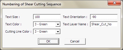
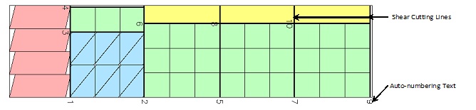
You are able to pre-define the text size, layer and color of the Auto-Numbering of the cut sequence/Cutting lines of shear-cuts here. When this “Shear Cut No.” button is clicked, the following dialog box is displayed. |
|
|
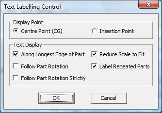
Display Point |
The location or display point of the text label. Two options are available :- •Centre Point (Centre of Gravity) or •Insertion Point. By default the text will be displayed “middle” justified from the display point. |
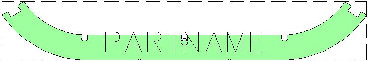
Along Longest Edge of Part |
“Along Longest Edge of Part” means that the text label will be displayed along the longer side of the Part’s smallest enclosing rectangle (from the “Display Point”). See examples below :- |
|
|
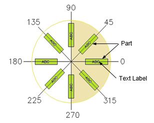
Follow Part Rotation |
Text will be displayed following the rotation angle of the Part. However, there is a display convention adopted for this setting. For examples :- •0 and 180 deg. are displayed as 0 deg •45 and 225 deg. are displayed as 45 deg •90 and 270 deg. are displayed as 90 deg •135 and 315 deg. are displayed as 315 deg….. and so forth.
If BOTH “Along Longest Edge of Part” and “Follow Part Rotation” /“Follow Part Rotation Strictly” check-boxes are marked, by default “Along Longest Edge of Part” setting will take precedence. |
Follow Part Rotation Strictly |
Unlike the previous “Follow Part Rotation”, this Text display option will display text following the rotation angle of the Part strictly. Therefore text will be displayed 0 degree if the part rotation is 0 degree. Similarly text will be displayed 180 degrees (upside down) if the part is rotated 180 deg. |
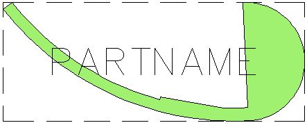
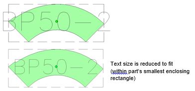
Reduce Scale to Fit |
If the part label is outside of the part’s smallest enclosing rectangle and if this setting is ON, then AutoNEST will automatically scale-down the text size such that the label is displayed within the part’s smallest enclosing rectangle. See examples below :-
|