|
|

|

|
|||
|
|
|
|
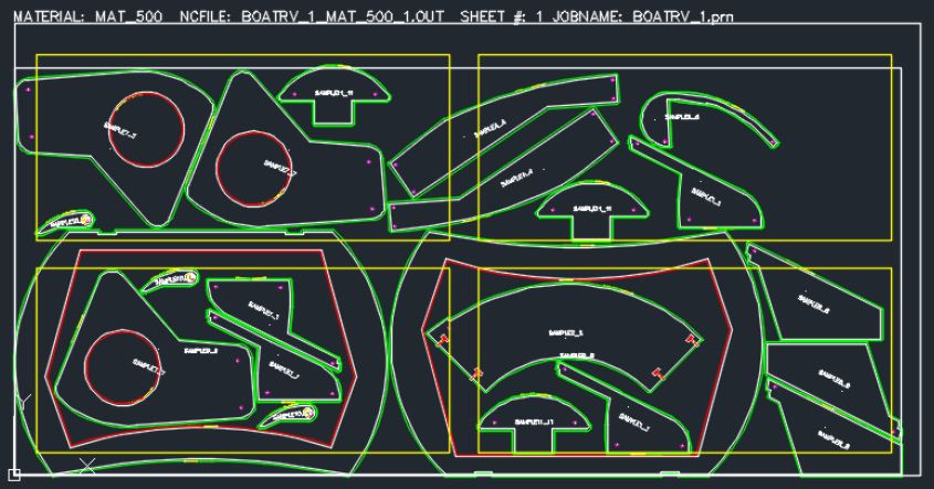
Small Part Control Nesting allows a user to define locations where they want small parts to be nested.
Note: In order to use the Small Part Zones option, you will need 'Rename Outside Layers' defined. Refer to the 'Job Settings' section for more information.
Part Area Definition
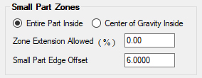
When a part is identified as small by the Rename Outside Layers option, the Small Part Zone feature place the small part within the boundary based on either the entire outside geometry of the part (Entire Part Inside) or on the parts identified center of gravity (Center of Gravity Inside). Default is 'Entire Part Inside'
Zone Extension Allowed (%)
Allows the user to apply a zone extension as a percent to the Small Part Zone. If the Zone Extension Allowed is defined as 10.0, it will allow a 10% extension around the defined Small Part Zone. For example, if the small part zone has a dimension of 10 by 10, the zone extension would allow nesting to look at an 11 by 11 zone.
Small Part Edge Offset
Defining a Small Part Edge Offset will use the material size and offset it by the number input here. Use this option to create a boundary based on the material size.
Create a Custom Small Part Zone
Custom Small Part Zones can be defined by creating an AutoCAD drawing and following these steps.
Create an AutoCAD Drawing
Create an AutoCAD drawing that defines the stock size and the small part zones.
When creating this drawing, the stock size needs to match the size of the material that it is being defined for. When the stock size is drawn, it will need to be located on a layer called SPCN_STOCK to identify the overall size of the material.
Next you will draw the small part zones with the geometry on the layer SPCN_ZONE. You can identify up to 4 unique zones.
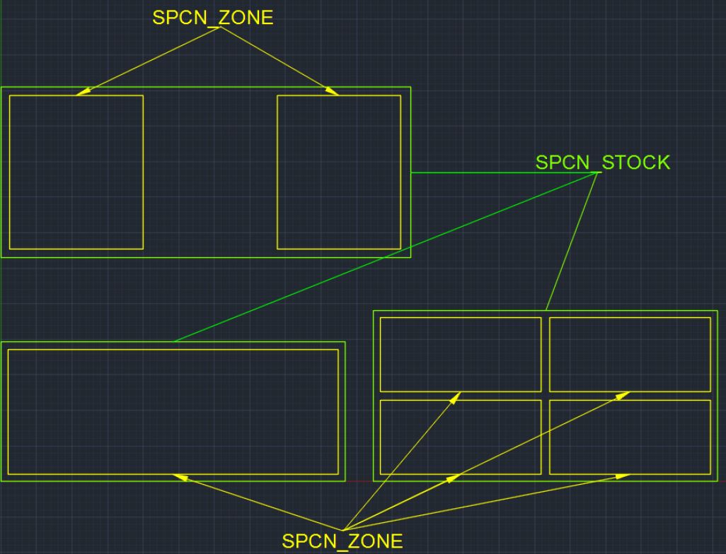
Note: The stock/material and the small part zones need to be closed geometry rectangles.
You will then need to save the drawing with a specific name. The name of the drawing will MUST to be the MATERIAL CODE as defined in the Material Database (See below).
Once the drawing has been saved, you will need to add the drawing to the Router-CIM Automation Suite job as a part. For more information on how to add a part to a job, go to the 'Add Part' section under 'Toolbar'.
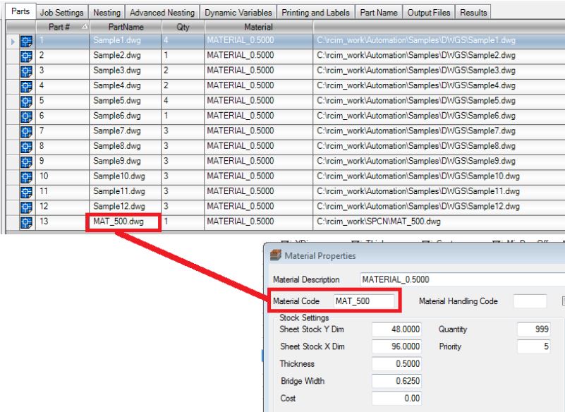
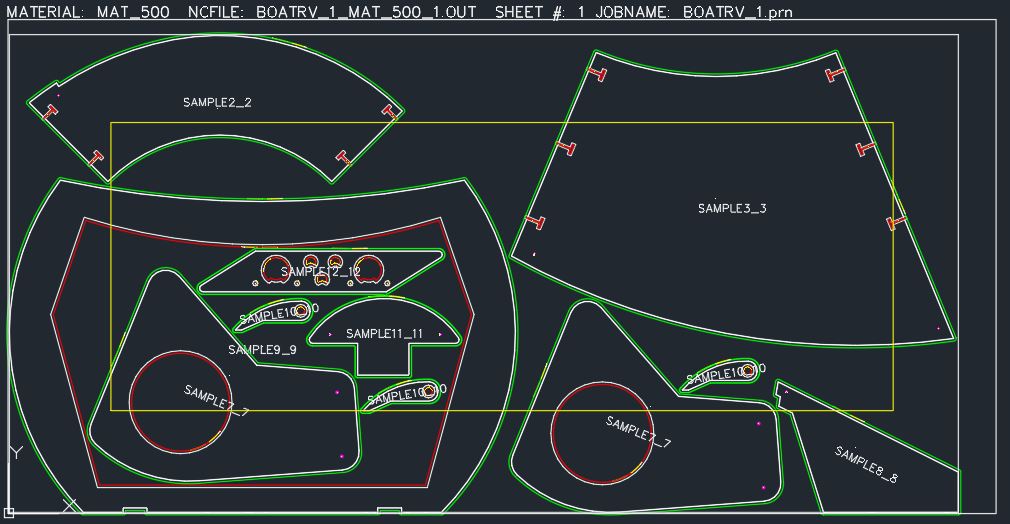
With the drawing added to the job AND placed on the correct material, custom Small Part Zones will be used. An example is shown here.