|
|

|

|
|||
|
|
|
|
The Part Name tab is to set the name of the part as it shows in the nested sheets AND will be the name of the code file if 'Code as Single Part' option is being used. For the code files, they will default with beginning with the letter S. SSample1.out. If you wish to change the prefix or suffix of the single code files, please refer to the variable 'Output Files' section.

There are 5 possible sections to compile the data embedded in the part name as it appears on the nested sheet. Each section will appear in the Sample Part Name box at the bottom to show an example of how the name might look should certain options be specified.
The default is to use only the Part Number.
The prefix for each section can be specified as a character you wish displayed between each field.
The following shows Section 1 set to Part Name instead of Part Number:
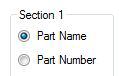
![]()
Changing Section 1 to Part Number and Section 2 to Part Name gives you this result:
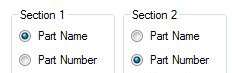
![]()
And using all 5 sections could give you the following result (which is a very long part name).
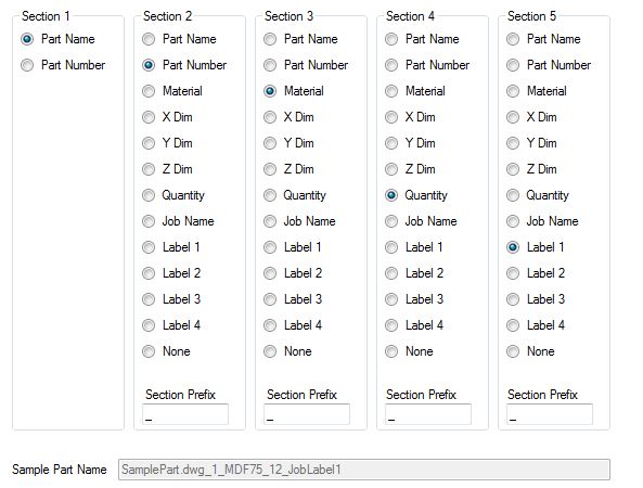
Keep in mind that this is to set the name of the part as it shows in the nested sheets. If you have small or narrow parts, and a lot of combinations to the name field, the text will overlap other parts and could become confusing.
To manually set a point for the part name to be placed on individual parts, you will need to add the variable *nestpoint* in the NCVAR file. Please go the Common Variables in Automation section to find out how to add this variable.
Once the variable has been entered and the value set to T, you will need to place an AutoCAD "point" on the part drawing itself in the location that you want the part name to be located. This "point" will need to be on the layer NESTCENTER that you create in the part's AutoCAD drawing. When labeling the part, Router-CIM Automation Suite will insert the part name at the "point" location you defined on layer NESTCENTER.
For information on how to insert points through AutoCAD, please refer to the AutoCAD Help file.