|
|

|

|
|||
|
|
|
|
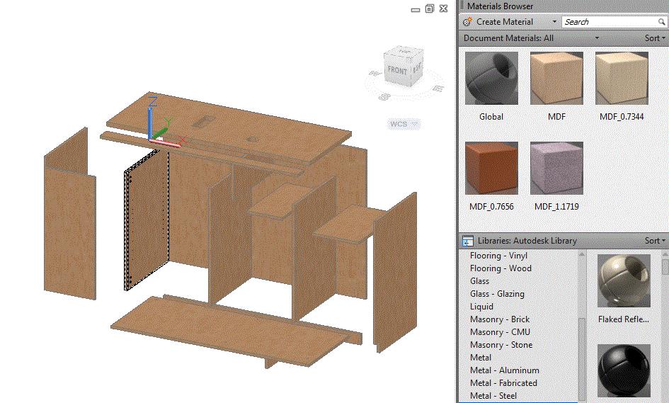
Steps to produce the figure shown:
•Select the Material Browser from the Render ribbon or type MATBROWSEROPEN at the command line.
•Type SV (if not already done) to show only the solids of the parts.
The materials defined in this figure have already been defined by the Materials Editor. Reference AutoCAD documentation on how to create materials.
Use the Realistic visual style.
It is suggested that the Materials Browser is placed on the right side of the screen and locked for ease of viewing. The Realistic visual style must be used in order to see the material on the parts.
There are naming rules that Solid-CIM 3D requires for material names. There can be material names that are generic such as “MDF” or material names that specify the exact thickness of a part using exactly four decimals in the name. Example: “MDF_0.7344”.
The actual visual representation of the material can be anything. Obviously, applying different visual representations for different materials would aid in the assigning of materials and the viewing of the parts.
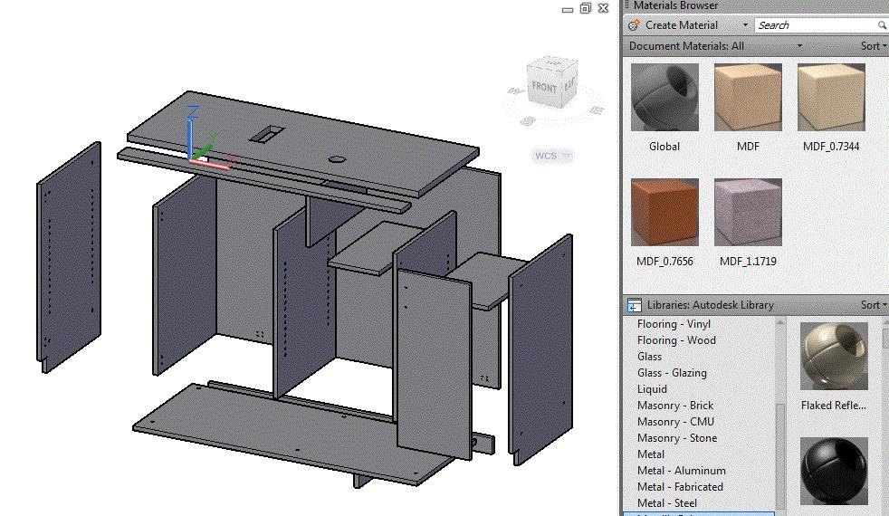
Reference AutoCAD’s documentation: Apply Materials to Objects.
Solid-CIM 3D works best with using a generic material name with no thickness in the name. Solid-CIM 3D will automatically add the thickness to the material name. In this example, we use the MDF material for all the parts shown. Material only needs to be added to the unique parts. Solid-CIM 3D will automatically assign the same material to the duplicate parts.
Apply a material to all the parts.
The figure shown has material applied to the parts.