|
|

|

|
|||
|
|
|
|
A veneer matched set/group is the combination of multiple parts that you want to be nested together in a set configuration so that they are machined from one section of a sheet.
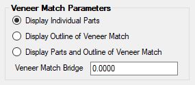
The result of the Veneer Match Parameters are shown here:
Display Individual Parts
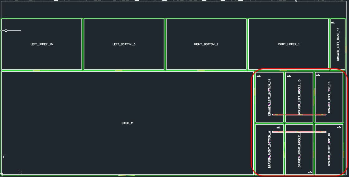
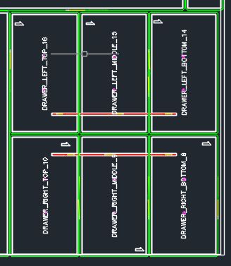
Parts are nested individually using the materials bridge width to separate the parts:
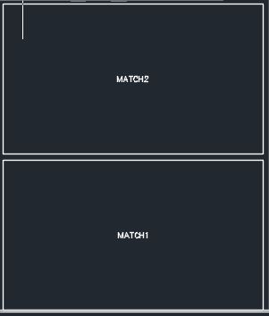
Display Outline of Veneer Match
Parts are not shown and an outline of the veneer match set is shown:
The layer used to define the outline of the veneer match is VENEER_OUTLINE.
Note: If 'Label Parts' is selected under the Nesting tab, the veneer match outline will be identified by the veneer match name per set.
Display Parts and Outline of Veneer Match
Parts are nested individually using the materials bridge width to separate the parts and an outline of the veneer match set is shown:
The layer used to define the outline of the veneer match is VENEER_OUTLINE.
Note: If 'Label Parts' is selected under the Nesting tab, the veneer match outline will be identified by the veneer match name per set.
Veneer Match Bridge
The information that is needed in order to correctly let nesting know what parts need to stay together can be accomplished in two ways.
1) Manually find the Identification (ID) points and fill in the correct Part Properties parameters for the Veneer Match function.
| 2) Use Solid-CIM 3D on a 3D Model/Assembly so it can define the Identification (ID) points for you so they can be imported to the right Part Property parameters. Refer to the Solid-CIM 3D Help Manual for more information on how to use the Veneer Matching feature through Solid-CIM 3D. |
Veneer Matching Considerations:
1)You cannot use ShapeDone with parts that will be veneer matched. If ShapeDone is turned on for those specific parts it will still be processed as if it was not turned on.
2)The spacing between each part that is veneer matched will match the material bridge width. If a different spacing is desired you can set the Veneer Match Bridge to the desired spacing for the veneer matched parts.
3)Veneer match rotation is defaulted to 0, if a different rotation is desired reference Figure 6 for how rotation works with veneer matched parts.
Manually Creating Veneer Matching Parts:
1)Create your individual parts that will be included in the final veneer matched part configuration. Each part should be in its own drawing for Router-CIM Automation Suite.
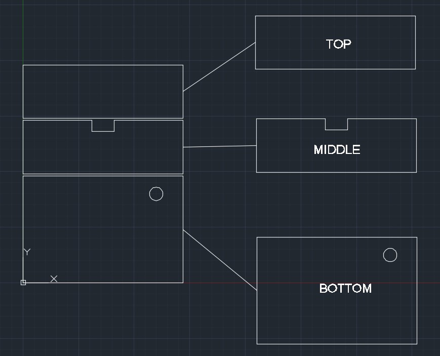
2)Once all of the parts are created, insert those individual parts into a new drawing in the configuration you would like nested. This is shown below, where we are using the three parts on the right: Top, Middle, and Bottom to make the configuration on the left.
Note: The drawing you are inserting the parts to be Veneer Matched will not need to be saved. This drawing is only used to obtain the information needed for the Veneer Matching Parameters.
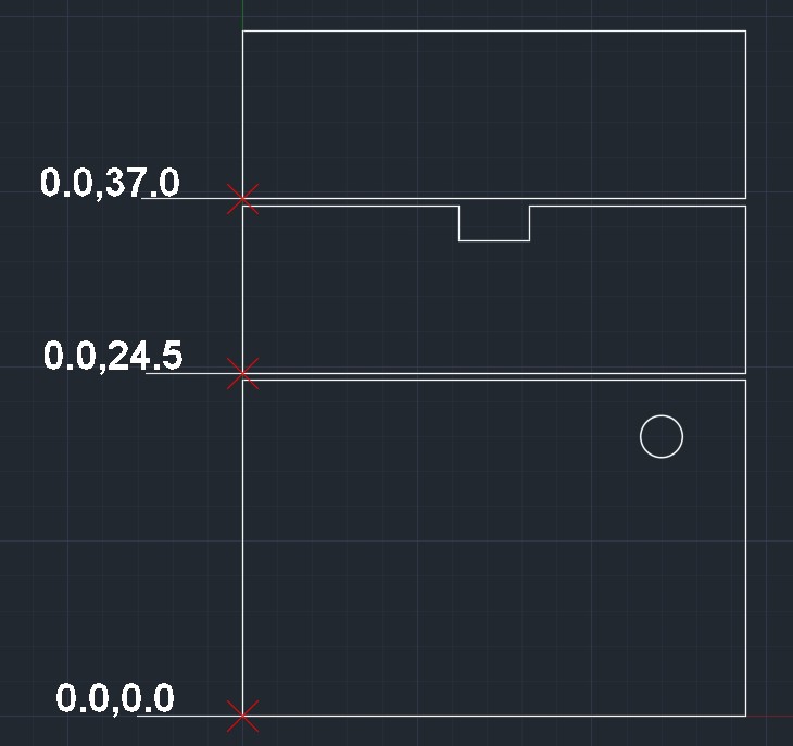
3) Once the parts are configured the way that you want them, like shown on the left of the above image, use the ID command you select the lower left point of each part, and record the X, Y, Z value. We are only looking for 2D points, so make sure you ignore whatever value represents the thickness of the part. In the example shown we are ignoring the Z-Value because the drawing is in the XY plane with thickness being the Z dimension. Below are the results for this command on the lower left point of each part.
Note: Make sure the parts are configured in the AutoCAD drawing as if they were laid out on the sheet of material you will be using. If the veneer/grain direction on the sheet of material follows the long side of the sheet, make sure the parts are configured to match.
4) Once you have the location point information for each part you should now bring these parts into Router-CIM Automation Suite.
5) Fill in the veneer match parameters for all parts that should be veneer matched for each individual part. These settings are located under the Part Properties of each part.
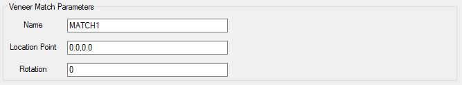
| There are three Veneer Match Parameters available: |
| A) Name (Required) - This parameter is used to define which parts need to be Veneer Matched when going to the nesting function. In this instance, all three parts are defined as MATCH1. The Veneer Match feature can handle multiple sets/groups in a single job. Each set/group would need it owns unique name in order for them to be nested correctly. |
| B) Location Point (Required) - This is the relative location of each part in regards to every other part in the veneer matched set/group. The appropriate format of this field is Coordinate 1 (X Axis) followed by a comma and then Coordinate 2 (Y Axis) (i.e. 3.0,4.0). No spaces are allowed. This information was obtained in step 3 of this section. |
| C) Rotation (If needed) - The first part in the veneer match set/group with a Rotation will be used to direct Router-CIM Automation Suite on how you want the veneer matched part rotated. All parts in the veneer match part should have the same number to avoid errors when processing. This is only needed if the parts in the veneer match set/group were not configured correctly to match the direction of the veneer/grain direction of the material being used. |
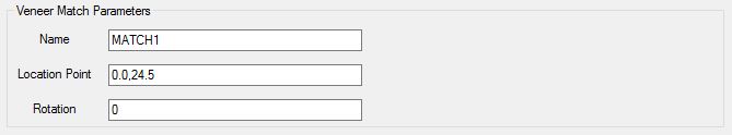
Part 1 (BOTTOM):
Part 2 (MIDDLE):
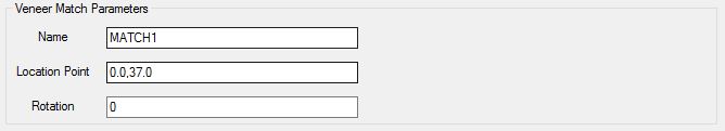
Part 3 (TOP):
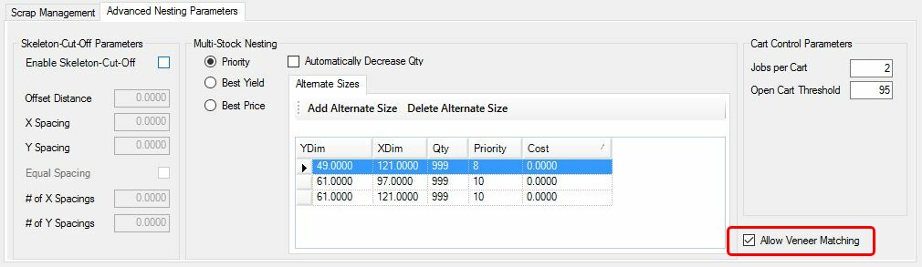
6) The final step is to configure your material to allow for Veneer Matching. Simply go into your material(s) that you will be using and under the Advanced Nesting Parameters for the material, check the box for 'Allow Veneer Matching'.
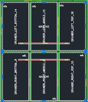
The result of the Veneer Matching process is shown here: