|
|

|

|
|||
|
|
|
|
|
Profile-Inside cycles will start the cut in a hole that has been created for the purpose of getting the tool down to the proper cut depth without plunging the cutter into the material. The cycle will start at the Safety Plane, plunge down to the Total Cut Depth inside the hole that has been created for that purpose. Then the cutter will machine a path to the start point of the shape and cut around the inside of the profile back to the start point and then back to the lead hole where it started and at that point it will retract back up to the Safety Plane.
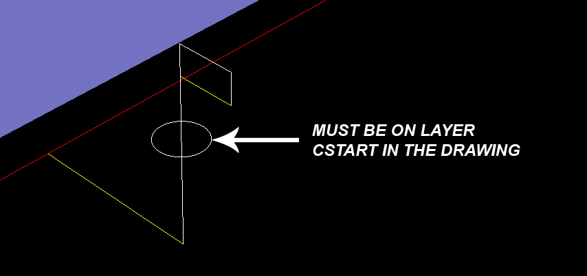
Profile-Inside Auto requires a circle on layer 'CSTART' in order to automatically have a starting hole location. The circle on layer CSTART should be drilled or milled out before this cut cycle occurs, insuring that the cutter has a safe place to plunge.
Note: Profile-Inside cycles cannot do multiple depths. Make sure the 'Depth Per Pass' is set sufficient to complete the cut in 1 pass. |

Profile-Inside-Automatic Cut Cycle

Profile-Inside-Automatic Cut Cycle
The following parameters effect the toolpath creation:
Offset Dim
The offset dim is the amount the toolpath is offset from the original geometry or Geoshape.
Normally this is set by Router-CIM depending on a number of features such as the Cutter Compensation setting and the cut cycle itself. For instance if Cutter Comp is set to Yes, then the toolpath will lie directly on top of the Geoshaped geometry with no offset.
You may substitute the parameters here for numeric values to suit you particular cutting needs.
The value set by default (FIRSTXY XYCUTLOC) is a macro setting that allows Router-CIM to handle the offset automatically and will usually not need to be changed.
See Offset Dim for more information.
Cut Side
Cut Side is the side of the Geoshape that the toolpath will be created on. Valid entries for this field are Outside, Inside, RH (Right Hand) and LH (Left Hand).
See the Cut Side section for more information.
Cut Direction
The direction of the cut can only be clockwise (CW) or counter-clockwise (CCW). This even applies to open shapes where this direction really has no meaningful relationship to the geometry selected. Any closed shapes should have the direction set accordingly and any open shapes should be set to CCW as all shapes in AutoCAD and Router-CIM are CCW by default.
See the Cut Direction section for more information.
Round Corners
If set to Yes, this option will round sharp corners with a radius of the value stored in the task *cutfil*. The default is 0.01 radius (in inch mode). This option will insert a fillet in all corners, so if you have an inside cut you will most likely cause an error when the tool tries to fit into that radius. If you have inside and outside cuts on the same shape and need to fillet the corners, use the AutoCAD Fillet command, then Geoshape and Cut the shape.
See the Round Corners section for more information.
XY Stock Allowance
Placing a value in this parameter will offset the tool path to leave material for a finish pass. For instance, placing .125 in the XY Stock Allowance and cutting a 6.4 x 4.0 shape will actually leave a part that is 6.25 x 4.25, by adding .125 to the offset of the tool path all the way around the part.
See XY Stock Allowance for more information.
Z Stock Allowance
Placing a value in Z Stock Allowance will change the Total Cut Depth by the number entered. You can use this if you want to leave a small amount of material on the bottom of a part, or if you intentionally want to overcut a part to be sure it is cut all the way through.
Entering a positive number will move the tool path UP in Z, leaving more material for a finish pass.
Entering a negative number will move the tool path DOWN in Z, past the normal Total Cut Depth.
See Z Stock Allowance for more information.
Lead Feed
This sets lead-in and lead-out feed rates. The default is 0.5, Router-CIM's standard 50% feedrate for lead-in and lead-out.
Setting a number between 0 and 1.0 will give you a percentage of the max feedrate (for instance 0.4 would be 40%).
Setting the number to a value greater than 1.0 will give you an exact feedrate. For instance 250. would generate F250. in the code.
See the Lead Feed section for more information.
**Changing values in the cycle parameters may yield unexpected results with some settings or on some geometry. Examine the toolpath and NC Code carefully before running your machine tool if you change these default settings.
