|
|

|

|
|||
|
|
|
|
When an MPR file is added to Router-CIM the MPR file will be converted to a drawing (DWG) file in the background, and you will see the drawing file added to the Router-CIM job. The drawing file will contain geometry that has thickness and is layer separated.
If the material that was specified in the MPR is found in the material database, then it will be used. If a MPR specifies a material that was not found in the database then the material will be put on the default material that was set for the job.
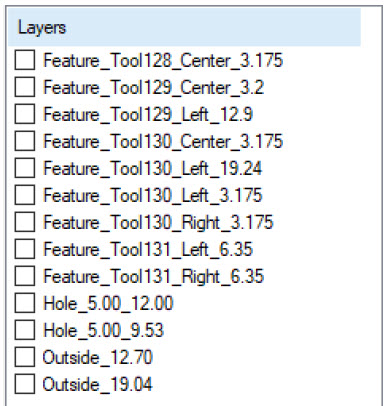
MPR to Drawing Layer Name Format:
Features found inside of the MPR file will be put on unique layers depending on the information found in the MPR file.
Contour features follow the format: “Feature_Tool_RadiusCompensation_Depth
Tool is the Tool Number
RadiusCompensation will be either Center, Left, or Right based on the parameters NOWRK, WRKL, and WRKR
Depth is calculated based on the Start Coordinate Z
Drill features follow the format: “Hole_Diameter_Depth
Both Diameter and Depth are generated from the tool found in the MPR file
Outside features will follow the format: “Outside_Depth
Depth is generated from the MPR file
Below is a screen capture from the DOIT editor for MPR files that were converted to drawing files.