|
|

|

|
|||
|
|
|
|
|
Fast Pattern Recognition is the same as regular Pattern Recognition, except that it substitutes fast feed moves for the rapid index moves between drills, which actually speeds up the overall drilling operations.
The Pattern Recognition cycle examines the drill holes on your part and the configuration of your drilling head(s) to determine the most efficient means of boring the selected holes. In order to use this function properly, the configuration of your drill heads must be set before you attempt to use this cycle. (See Note below.) Once configured, pick Pattern Recognition from the Cycle menu, choose Cut, and then select the holes to be bored. Pattern Recognition will load into memory, determine the most efficient route, and then proceed to bore the holes. The lead spindle in the group will have the tool path displayed on the screen; the others in the group will change colors to show they have been processed. The gang drill drawing will be provided to you by CIM-Tech following the specifications of your machine tool. Drill holes processed with Pattern Recognition need not be Geoshaped, and should be given thickness equal to their depth (negative Z value). |
Note: The size of the holes on your gang drill drawing in your machine-specific default drawing MUST BE THE SAME SIZE as the holes in your current drawing for Pattern Recognition to work. You do not need to add any tool numbers in the Control Panel, as Pattern Recognition will find the tools it needs and add them automatically.
Note: Pattern Recognition is only available on certain machine types that allow for an optimized boring block. Please review your Post Processor's Application Notes to see if this cycle is available with your machine.

Typical Pattern Recognition Part.

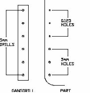
Match the drill block drawing to the drills in the machine.

Result of Pattern Recognition.
In the example above, the two rows of shelf holes are 32mm apart (1.2598") and there are two rows of 14 each. There are also two sets of hardware holes with sizes that do not match the shelf holes. With the drill block shown above, there are 7 drills in a row that match the shelf holes, so the drill block only drops twice on each row, drilling 7 holes each time. It then drills each of the hardware holes one at a time. In this instance, there are 10 drill cycles for a total of 34 holes.

Fast Pattern Recognition Parameters
Pattern Recognition - Tolerance Variable (*pat_fuzz*)
For Pattern Recognition to work properly, the diameter of the holes in your current drawing must be the same size as the holes on your gang drill drawing in your machine-specific default drawing (which is loaded into your current drawing upon loading Router-CIM). There is a tolerance built into the system, for the diameter of the holes, that is set to 0.05. This variable is *pat_fuzz* in the NCVARS. Under normal circumstances this need not be changed. But, if you have tools of a similar size (i.e. within .05 in radius or diameter) then Pattern Recognition may choose the wrong tools to complete its boring operation. Generally, if you are using all inch or all metric this will not be a problem.
Example: There are six drills on the gang drill with 5mm diameter drills in them. The part has both 5mm and 0.125 diameter holes in it. The difference between these two diameters is within the 0.05 tolerance, so Pattern Recognition will see them all as one size. Therefore, all six drills will drop and drill all six holes and all hole diameters will be 5mm, which is incorrect.
The following parameters effect the toolpath creation:
Index Speed
This is the fastest speed that you want the machine to achieve between the drilled holes. This feedrate will take place of the rapid traverse move between cuts and during the retract of the hole. If the machine can make a fast linear move between the cuts, usually this will reduce the overall cycle time of the drill moves.
Fastdrill
This engages the fast drill cycle. Entering Y will turn it on. Entering N will turn it off and the g-code will revert to the 'Drill Motions' cycle.
**Changing values in the cycle parameters may yield unexpected results with some settings or on some geometry. Examine the toolpath and NC Code carefully before running your machine tool if you change these default settings.