|
|

|

|
|||
|
|
|
|
Once the shapes have been geoshaped, you will be able to set up the cut knowledge necessary to cut your shapes. All of the standard cut cycle are available to use for horizontal cutting and only a few considerations are necessary to ensure a proper cut. On the status screen, you should select your cutting tool and cycle. In order to ensure that the horizontal tool will clear the part in the Z axis, a 4 axis safe height is necessary. The value stored here will be output as the Z clearance height generated before and after the cut. In the lower right side of the screen there is a Plane Detect checkbox that, when activated, will recognize which plane the geometry is drawn on, and generate the correct code for that particular face.
Both of these items, the 4 axis safe and the Plane Detect should be used when making a horizontal cut.
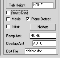
The 4 Axis Safe and Plane Detect settings on the Status Page.
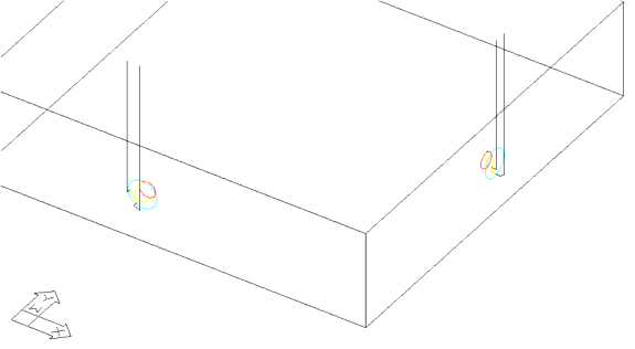
Producing the cuts shown below.
Cutting Planes
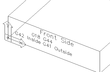
When making cuts on the sides of a part, the geometry may lie on one of the planar faces that the machine tool can recognize.
On the Fanuc control, the front side of the part will be the G18 plane and use the G44 command for horizontal length compensation, and cutter compensation will use G42 for inside cuts and G41 for outside cuts.
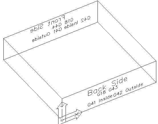
The Back Side would also be the G18 plane, but will use the G43 command for horizontal length compensation and G41 for cutter compensation on inside cuts and G42 on outside cuts.
The difference in the G43/G44 commands is so the action of the tool as it sets the horizontal length compensation is always the same and POSITIVE values are placed in the offset registers in the controller.
On the left and right sides of the part, the G19 Plane will be called. On the left side, the G19 plane uses the G44 command and G42 inside and G41 on the outside, just like the front face does. The right side of the part uses G19 with G43 and G41 on the inside and G42 on the outside cuts, just like the back side.
In addition to the commands listed some of the G02 and G03 commands for arcs will be reversed as well.
The post processor will generate arcs in the proper direction for the plane selected. If a helical cut is made on a G18 or G19 plane, then G01 point to point moves will be made for the helical portion of the cut and G02/G03 moves made for any flat, planar moves by the cutter.
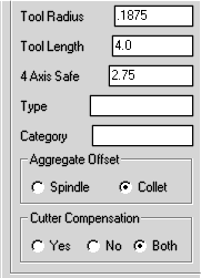
If the geometry drawn does not lie directly on the G18 or G19 plane, and Plane Detect is checked, then the cuts will be generated as point to point G01 moves in the G17 plane. If this method of cutting is necessary, then another switch is located on the status page that will allow an offset value based on the Tool Length field. The G43/G44 cannot work if the cut is not planar. To accomplish the offset that would normally be done with the G43/G44 command, you must set the toggle Aggregate Offset to Spindle instead of Collet so that the cut is shifted by Tool Length away from the shape.
In the picture shown, the parameters are set as follows:
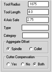
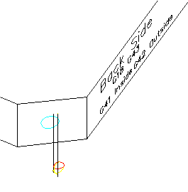
Setting the Aggregate Offset ensures the offset shown. The Tool Length offset of 4.0 is the distance from the cut to the shape. If the safety plane value is *.25, the depth of cut is -.5, then the tool moves .25 inches away from the shape, then down to the cut position in X and Y, and then lead in from the .25 inch safety plane into the part .5 and then lead out to .25 away from the part and up to Z 2.75 inches (assuming Z0 is top of part). If the Z0 is the top of the table, then the Z value at the start and end will be 2.75 plus the part thickness.