|
|

|

|
|||
|
|
|
|
ConvertPart is a function that allows the user to convert part profile in DXF file format to Part (.VEC file format).
Similarly, it allows user to convert Parts (.VEC file format) back into DXF format.
If the Parts have markings, make sure you set the ‘Layer Name’ & ‘Color’ filters of the parts so that ConvertPart is able to differentiate the part profiles from the markings. You define the layer names and colors in Sysdata “Input Part /IR-Stock – Layer Setting”.
Select the ConvertPart command icon from the icon menu or from the AutoNEST pulldown menu. The following dialog box will appear:
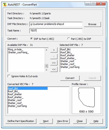
Parts Directory |
Display the default part directory as set in the Sysdata. In this case, it is also the target directory where all converted file will be saved. |
Task Directory |
Display the default task directory as set in the Sysdata. By default the Task created by ConvertPart will be saved onto this directory. |
DXF File Directory |
To type in or click on the |
Task Name |
You are able to define the Taskname in this dialog. This name will be carried forward to TaskEdit. |
Convert DXF to Part (.VEC) |
Check this radio button to convert DXF file format to Part (.VEC). |
Convert Part (.VEC) to DXF |
Check this radio button to convert Part (.VEC) file format to DXF. |
Available DXF/VEC File |
Display a list of available files found in the Part Directory (This will depends on which conversion has been chosen). You can select one or more files to be converted by highlighting the filenames and then the |
Selected DXF/VEC File |
Display a list of files selected for the conversion. You can select the filenames and click the |
Ignore Holes and Cut-outs |
If this check-box is marked, holes and cut-outs will not be converted. |
Converted VEC/DXF File |
This will show files that have been converted successfully. |
|
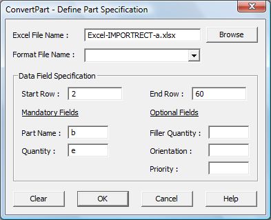
This button will enable you to define the part quantity, orientation constraints, part priority …etc for each and every converted parts via an Excel spreadsheet. The following dialog will appear when this button is clicked. |
|
|
Excel File Name |
Click the ‘Browse’ button to select the Excel file that contains the art information. |
Format File Name |
Choose an existing Format filename if it has been saved previously. Otherwise leave it blank. |
Start Row End Row |
The first starting row number and the last row number of the parts. Only numeric input is accepted. |
Mandatory Fields: Part Name Quantity |
Indicate the corresponding Column numbers as in the Excel file for Part Name and Quantity. |
Optional Fields: Filler Quantity Orientation Priority |
These are optional fields. Indicate the corresponding Column numbers as in the Excel file for Filler Quantity, Orientation and Priority, if they are available. |
|
Click this button to proceed to TaskEdit. |
Click this icon to view error messages, if any. This is especially helpful as it will give a list of the filenames that cannot be converted for certain reasons. |
If you have not defined the Part Information via the button of the same name, when you click “Next” a dialog will appear to enable you to enter the quantity of all the converted parts. Default is “1”. After that the TaskEdit dialog box will appear.
If any Part has a different quantity, you can change it in TaskEdit where you will specify the Stock and other cutting information.