|
|

|

|
|||
|
|
|
|
The example given here will show a containment polyline controlling the area where the tool path is created. The polyline must be closed, and actually be a polyline. This is easy to achieve if you are using a circle, ellipse or some other irregular shape or combination of lines and arcs, you can always Geoshape them and use the result from Geoshape for the containment polyline.
In this instance, the MCADTPC.dwg is used with a circular containment area created.
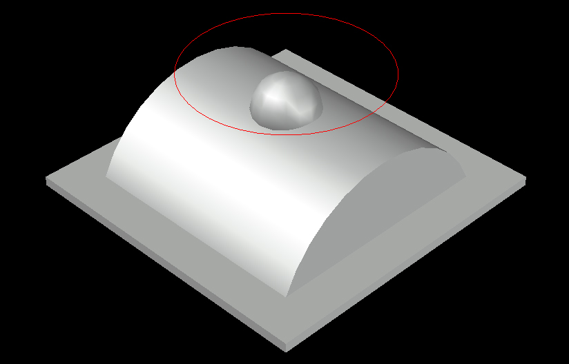
The containment polyline has been created at Z0 and so is above the part.
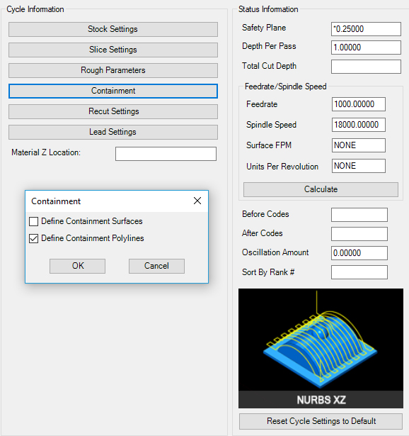
The cut settings are set up with the Nurbs XZ cycle defaults, but with a Containment Polyline selected in the Containment options.
Select Cut, and when prompted to redefine the surfaces, answer Yes. Select the green solid for the part.
You will be prompted to input the Surface Tolerance, use .005.
Enter Surface Tolerance <0.00050000>: .005
Next you will be prompted to select the Containment Polyline(s), select the circular shape above the part.
You should see a tool path similar to the one shown here:
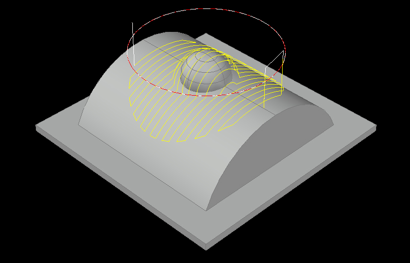
If there are any areas where the tool cannot continue its path without crossing the containment line, the tool will be forced up to the Safety Plane and then it will move over to the next area where it can continue the path. This is to avoid gouging the part or violating the containment polyline.