|
|

|

|
|||
|
|
|
|
For each Cluster, the following files are required :-
•.VEC of the individual parts
•.VEC of the Cluster
•.CLS of the Cluster
Take for example, the Cluster-part below which consists of 3 nos of Part C3 and 2 nos of Part C4. The .CLS and .VEC of the Cluster is described below.
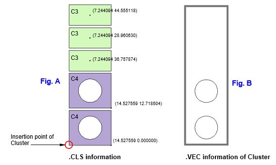
.CLS file contains the relative co-ordinates and angle of each of the individual part’s position to the Cluster’s insertion point. (See Fig. A above)
1 #
2 # AutoNEST V9 ENGLISH
3 # Cluster Name = ClusterName.cls
4# First Line = Part-name, Relative-X-coordinate, Relative-Y-coordinate, Rotation-Angle
5#
6 C3 7.244094 44.555118 0.000000
7 C3 7.244094 28.960630 0.000000
8 C3 7.244094 36.757874 0.000000
9 C4 14.527559 12.718504 90.000000
10 C4 14.527559 0.000000 90.000000
(Note: The above line numbers are strictly for referencing purposes, they do not appear in the file.)
Description of .CLS File Format
Line 1 to 5 |
Lines start with "#" character denote comments. There is no limit to the number of comment lines. The 'AutoNEST V9 English’, must be in one of the comment lines. The ‘V9’ reference number is used to check the different formats of files of different software releases. ‘English’ indicates what language version of current AutoNest you are using. |
|
|
||
Line 6 to 10 |
1st parmeter : Part name 2nd parameter : Relative x-ordinate of Part’s insertion point to Cluster’s insertion point. 3rd parameter : Relative y-ordinate of Part’s insertion point to Cluster’s insertion point. 4th parameter : Rotation angle of Part in degrees |
|
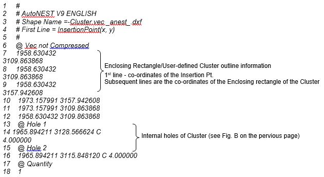
.VEC file of a Cluster contains the enclosing rectangle of the Cluster or user-defined outline of the Cluster and the internal holes information. (See Fig. B above)