|
|

|

|
|||
|
|
|
|
A .JOB file will contain all the relevant controlling parameters of the nesting for a particular task – as captured in the dialog boxes when TaskEdit is invoked. The format of the file is as follows:
1 #
2 # AutoNEST V9 ENGLISH
3 # Job Name = EXAMPLE1
4 # Next 6 lines = No of Distinct Shapes, No of Distinct R-Stock & I-Stock,
5 # Cutting Gap, Edge Allowance X and X1,
6 # Edge Allowance Y and Y1 Control Parameter
7 4
8 2 2 1
9 5.0000 0.0000
10 10.0000 10.0000
11 10.0000 10.0000 0.0000
12 C R 1 3 0 2 1 0 600.0000 600.0000 2 15.0000
13 1200.0000 x 2400.0000 10 1 77.00 0 0.00
14 1500.0000 x 3000.0000 10 1 99.00 0 0.00
15 &I-STK 1 1 Y
16 &I-STK5 1 1 Y
17 20 W17 (0 90 180) Y 1 W17 0 1 5
18 20 W18 (ALL) Y 1 W18 0 1 5
19 10 W20 (step 10 0 180) Y 1 W20 0 1 5
20 20 W23 (step 1 0 90) Y 1 W23 0 1 1
21 BRIDGE 5.0000 20.0000 50.0000 4
22 SKELETON-CUT 850.0000 750.0000 3.0000 1
(Note: The above line numbers are strictly for referencing purposes, they do not appear in the file.)
IMPORTANT: Do not use 'Tab' characters when you are constructing this file with a text editor or word processor. Instead use ordinary spaces.
Line 1 to 6 |
Lines starting with "#" are comments. There is no limit to the number of comment lines. The 'AutoNEST V9 English’ must be in one of the comment lines. The ‘V9’ reference number is used to check the different formats of (.JOB) files for different software releases. ‘English’ indicates what language version of current AutoNest you are using.
|
Line 7 |
Number of distinct parts (Range: 1 to 1000)
|
Line 8 |
The 1st digit represents the number of distinct regular stocks Range : 1 to 5000 (max. value as set in ANEST.SYS)
The 2nd digit represents the number of distinct irregular stocks Range : 1 to 5000 (max. value as set in ANEST.SYS)
The 3rd digit represents “Multi-Stock Control” 0 - means “Auto” 1 - means “Best Yield” 2 - means “Lowest Cost”
“Auto” is the default setting and is the fastest option where the nesting engine will appraise the parts and stocks and then automatically selects the largest suitable Stock to nest.
“Best Yield” - in this option the nesting engine will iterate through each Stock size to nest the available parts. For each nested Stock , it will compare the nested utilization area of Stock and then select the one with the highest utilization. It will continue to iterate until all the parts or stocks are used up.
“Lowest Cost” - in this option the nesting engine will iterate through each Stock size to nest the available parts. For each nested Stock, it will compare the Nested Area per Cost of Stock and then select the one with the highest Nested Area per unit cost.
For this option to work, the “Cost per Stock” must be specified.
Both the “Best Yield” and “Lowest Cost” will take a longer time to nest.
***The more the number of distinct Stocks, the longer it will take to nest for “Best Yield” or “Lowest Cost” options***
If either “Best Yield” or “Lowest Cost” option is selected, the Stock Priority will be ignored.
|
Line 9 |
1st parameter denotes “Cutting gap” (Max field length : 14 real nos.) 2nd parameter denotes “Shear Blade Limit”. (Max field length : 14 real nos, >=0.0) If this value is “0” - it means NO shear nesting required; if greater than “0” then it means “Yes” to shear nesting.
|
Line 10 |
Edge allowance [x] and [x1] (Left and right side of the regular stock) Max field length: 14 (real nos.)
|
Line 11 |
Edge allowance [y] and [y1] (Bottom and top of the regular stock) and Edge allowance of irregular stock. Max field length: 14 (real nos.)
|
Line 12 |
Nesting control parameters. The 1st parameter can be: ‘D’ - means single part nesting with highest Density (in single array) ‘M’ - means single part nesting with Maximum quantity (in single array) ‘C’ - means single part nesting with Combination of density & maximum qty (in mixed array) ‘E’ - means extension - long nest.
|
|
The 2nd parameter is to specify which type of stock to be used first if there are both Regular Stock and Irregular Stock in the same job/ task. ‘R’ - means nest all Regular Stocks first before any Irregular Stocks ‘I’ - means nest all Irregular Stocks first before any Regular Stocks.
|
|
The 3rd parameter is for Packing Start Point 1 Left Bottom 2 Left Top 3 Right Top 4 Right Bottom
|
|
The 4th parameter is for Packing direction control 1 Horizontal Packing 2 Vertical Packing 3 Auto (System Control) 4 Horizontal Packing for All Stocks 5 Vertical Packing for All Stocks
|
|
The 5th parameter is for Common Line option 0 Without Common Line Consideration 1 With Common Line Consideration
|
|
The 6th parameter is for Mirror option (Single part only) 0 Do NOT allow Part Mirror 1 Allow Part Mirror 2 Nest Half Quantity with Mirrored Parts
|
|
The 7th parameter is for Ignore Part Hole option 0 Ignore ‘Hole’ of part (will not nest any parts inside part holes) 1 Do NOT ignore ‘hole’ of part (will nest smaller parts inside part holes)
|
|
The 8th parameter is for Save Remnant option 0 Do NOT save remnant stocks 1 Save remnant stocks into .STK files.
|
|
The 9th and 10th parameters are for Min. Remnant Size in X and Y. Only remnant stocks that are greater than this Min. Remnant Size will be saved into .stk files onto the default Part/ Ir-Stock directory and provided the “Save Remnant” option (8th parameter) is set to 1.
By default these remnants will be saved onto the Part/ Irregular Stock directory. The names of the remnant stocks will be Taskname_remnant1-1.stk, Taskname_ remnant2-1.stk, Taskname_ remnant2-2.stk and so on. The naming convention is as follows :- *_ remnant(LAYOUT_NO)-(NO) where “remnant” is the default name as defined in the 6th parameter of @REMNANT_CONTROL in ANEST.SYS.
In addition, a Task will automatically be created using the default name ‘Taskname_rem.job’ onto the Task directory.
The 9th and 10th parameters are for Minimum Remnant Size in X and Y. Only remnant stocks that are greater than this Min. Remnant Size will be saved into .stk files onto the default Part/ Ir-Stock directory and provided the “Save Remnant” option (8th parameter) is set to 1.
|
|
The 11th and 12th parameters are for ‘Parts Priority Control’. 11th parameter is for “Max. No. of Priority per Stock” (Integer >=0 12th parameter is for “Min. Nest-able Remaining Space” percentage. (real nos.)
“Max. No. of Priority per Stock” enables you to limit the no. of Parts of different priorities to be nested into a stock.
This is to avoid the confusion on the production floor where the operator, after cutting has to sort the parts and placed them into their respective “carts”.
“Minimum Nest-able Remaining Space” percentage – is the parameter for the remaining space after ALL the parts of the specified Priority have been nested onto the stock.
If 0 is defined, then any remaining space is considered “nest-able”, AutoNEST will try to find suitable parts to fit onto the remaining space.
If 10 is defined, the remaining space must be >=10% of the stock size to be considered “nest-able”, AutoNEST will then try to find suitable parts to fit onto the remaining space.
If 100 is defined, then any remaining space is considered NOT “nest-able”, AutoNEST will not attempt to nest into the remaining space after ALL parts of the specified priority have been nested.
|
Line 13-14 |
A list of distinct regular stocks /plates. Only the first 5 parameters are mandatory. Each line has the following format:
Stock-Width x Stock-Length Quantity Priority Cost-per-Stock 0 0.0 0 0.0 No-of-Small-Part-Zones X-Y-Coordinates-of-SP-Zone1 X-Y-Coordinates-of-SP-Zone1 X-Y-Coordinates-of-SP-Zone2 X-Y-Coordinates-of-SP-Zone2
The first 2 parameters are for Width x Length of stock plate or sheet.
3rd parameter is the Quantity of the stock plate /sheet.
4th parameter is the Priority of the stock plate /sheet. 1 has the highest priority whereas 99 has the lowest priority. This refers to the priority for regular stocks only.
5th parameter is the cost per stock plate /sheet.
6th & 7th parameters are currently used in AutoNEST FX. (not applicable here)
8th & 9th parameters are newly added parameters for future use.
10th parameter : No. of Small-Part Zones (1 to 4)
11th parameter : X & Y co-ordinates of the bottom left corner of Small-Part Zone 1 with reference to the bottom-left corner of the sheet.
12th parameter : X & Y co-ordinates of the upper right corner of Small-Part Zone 1 with reference to the bottom-left corner of the sheet.
13th parameter : X & Y co-ordinates of the bottom left corner of Small-Part Zone 2 (IF APPLICABLE) with reference to the bottom-left corner of the sheet.
14th parameter : X & Y co-ordinates of the upper right corner of Small-Part Zone 2 (IF APPLICABLE) with reference to the bottom-left corner of the sheet.
|
Line 15 - 16 |
A list of distinct irregular stocks (ir-stock). Each line has the following format:&ir-stock Quantity Priority Rotate-able
‘&’ is a prefix to differentiate the irregular stock from the regular stock.ir-stock is the .STK file name (ir-stock). The .STK file stores the ir-stock geometry profile.
Quantity refers to the quantity of the irregular stock.
Priority of the ir-stock to be nested. 1 has the highest priority whereas 99 has the lowest priority. This refers to the priority for the irregular stock.
Rotate-able has two options. “Y” means able to rotate the ir-stock and “N” means no rotation of the ir-stock.
|
Line 17-20 |
A list of distinct Parts.
Number of lines depends on number of distinct Parts. Each line has the following format:
Part-quantity Part-name (Orientation constraints) Pairing Priority Block-name Filler-quantity Support+180 Step-angle
Part-quantity - integer number (range: 1 - 9999) (Note: for Single Part tasks of fixed size stocks, part-quantity can be ‘M’ to indicate unlimited quantity of the Part)
Part-name - string, 30 characters long (no space characters allowed)
|
|
Orientation constraints - there are 2 formats to define orientation constraints. Both are acceptable and can co-exit in the same file.
Format A Combination of any angles between 0 and 360 (separated by SPACE such as :- (30 60 90 180 …) or (ALL)
Format B This new format is helpful if the Orientation angles consist of a long list and if the angles increase by a constant value. (step 10 0 180)
where: step is the reserved word to denote “increment angle” 10 is the increment angle (must be greater than 0 and a positive value) 0 is the Start Angle (real nos., range -360 ~ +360) 180 is the End Angle (real nos, must be greater than Start Angle)
If represented in Format A …. (0 10 20 30 40 50 60 70 80 90 100 110 120 130 140 ….…180)
|
|
Pairing - ‘Y’ means allow part pairing. ‘N’ means do not allow part pairing. Currently, not in use.
Priority - Priority of the parts to be nested. 1 has the highest priority, 2 has the second highest and so on.
|
|
Block-name - Part details block name. Part detail block is a DWG file containing more detail information of the part. In the current version, it will be the same as Part-name.
Filler-quantity - integer number (range: 1- 9999). Additional quantity for filling up available space.
Support+180 - 1 means allow the part orientation angle + 180 degree. Eg. if part allows 30 degree orientation, 30 + 180 = 210 degree will also be allowed. 0 means “No” to “+180” degrees for part orientation.
Step-angle - an incremental step angle for seeking the best nesting pattern. Reducing the step-angle will have higher chance to get a better nesting result but it will also increase the nesting time.
|
Line 21 |
Auto-bridge parameters The 1st parameter indicates starting of Auto-Bridge parameters. The 2nd parameter is the bridge width. The 3rd parameter is the minimum corner offset. The 4th parameter is the minimum angle (range 45~90 deg). The 5th parameter is the maximum number of bridges per part. (See below for illustration of these parameters)
|
Line 22 |
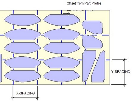
Skeleton-Cut-Off parameters The 1st parameter is the X-Spacing or No. of X equal spacings. The 2nd parameter is the Y-Spacing or No. of Y equal spacings. The 3rd parameter is the offset distance from part profile or skeleton-bridge. The 4th parameter : 1 indicates that 1st & 2nd parameters are real values. 2 indicates that 1st & 2nd parameters are actually no. of equal spacings for X and Y respectively, not the real values. (See below for the illustration of Skeleton-Cut-Off parameters) 5th parameter – Minimum area of Scrap-pocket 6th parameter – Maximum area of Scrap-pocket 7th parameter – Minimum length of Scrap-pocket |
Illustration for Auto-Bridge Parameters
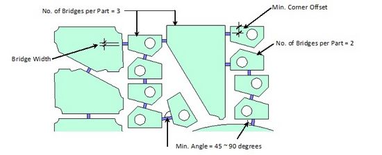
Illustration of Scrap-Pocket
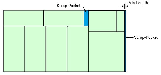
Illustration for Skeleton-Cut-Off Parameters