|
|

|

|
|||
|
|
|
|
|
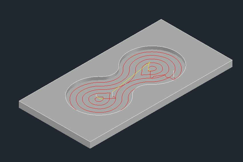
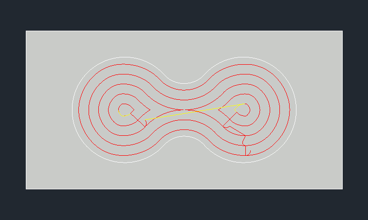
Advanced 2D Pocketing uses advanced algorithms based on the wire frame input geometry and contains many options to control the creation of the tool path than the other pocketing cycles. This method allows for more complex geometry to be handed to the tool path generator. The Advanced 2D Pocketing utilizes numerous parameters to generate the most efficient toolpath around a pocket. There are parameters to control the lead in motion, stepover distance, stepover type, and more.
The Advanced 2D Pocketing will start at a point inside the pocket and create offset tool paths, moving toward the outside of the pocket. |

Advanced-2D-Pocket-Parameters
The following parameters effect the toolpath creation:
The value entered here will be added to the cut offset to provide material left for a clean up pass on the pocket with a separate tool.
This value defines the stepover made after each offset.
1) Default of TW75 will step over by 75% of the tool diameter
2) Number followed by the % sign. This needs to be entered as a percent number such as 25% or 50%. This will stepover the percentage of the tool diameter
3) Number only. You can identify a specific stepover offset by just putting in the value as long as it does not exceed the diameter of the tool. Value of 0.25 would stepover 0.25 regardless of the tool diameter.
|
|
|
|
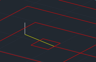
Direct Stepover |
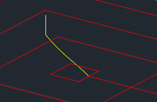
Blended Spline Stepover |
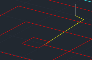
Retract to Feed Distance Stepover |
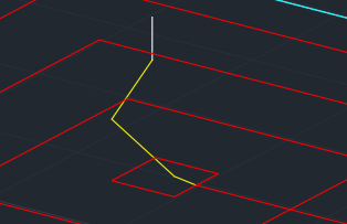
Retract to Clearance Area Stepover |
When set to “Y”, the toolpath will be extended into corners if the stepover does not reach.
The value represents if the cutting cycle will be doing Climb (CCW) milling or if you want the cutting cycle to do Conventional (CW) milling when pocketing inside geometry.
This sets lead-in and lead-out feed rates. The default is 50%. Setting this parameter to any number will override the lead-in feedrate to the number specified. Setting this parameter to a percentage, 25% (must include the % symbol) will adjust the lead-in based on the feedrate identified by the percentage defined on CNC machines with this capability.
This parameter defines the type of entry move the toolpath will make when making its initial approach.
The possible options are:
1) Automatic – The approach type will be picked automatically to avoid collision
2) Line – The ramp move is a slanted line when a Lead-In Angle is used
3) Helical – The ramp move is helical
4) ZigZag – The ramp move is alternating slanted linear moves in opposite directions
5) Profile – The ramp follows the toolpath contour shape while gradually plunging
|
|
|
Lead-in Line No Angle |
Lead-In Line 30 Degree Angle |
Lead-In Helical 30 Degree Angle
|
|
|
|
Lead-In ZigZag 30 Degree Angle |
Lead-In Profile 30 Degree Angle |
|
The parameter will need a numeric value defining the degrees of the ramp such as 30 or 45.
**Changing values in the cycle parameters may yield unexpected results with some settings or on some geometry. Examine the toolpath and NC Code carefully before running your machine tool if you change these default settings.