|
|

|

|
|||
|
|
|
|
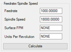
These fields are useful for calculating feed rates and spindle speeds based on a tooling/material parameter referred to as Constant Surface Speed.
Surface Feed per Minute and Units per Rev are variables based on the size of each tool, that your tool bit manufacturer can supply you with.
The calculation of Feedrate and Spindle Speed can now take place using the Surface FPM and the Units per Rev fields. Simply input the Surface Feed per Min. and Units Per Revolution in their respective fields, click on the Calc button, and Router-CIM will input the correct feedrate and spindle speed automatically.
This Feedrate and Spindle Speed can be saved with your knowledge and used in future cutting operations.
NOTE: The actual settings input into the Surface Feed per Min. and the Units per Rev fields are not saved in the knowledge as they are used for calculation purposes only!)
Following is some information about Feeds and Speeds copied from the Onsrud Cutter© manual that may prove helpful in better understanding Surface Feed per Min. and Units per Rev.
To understand the concept of feeds and speeds, it is necessary to visualize what is occurring at the cutting edge of the tool. A chip of material is being removed from the base part. The size and thickness of the chip is controlled by the speed of the rotation speed of the spindle and the forward movement caused by feeding the tool into the material. If there is one flute, then the chipload is equal to the amount of travel in one revolution of the spindle. If there are two flutes, then there are two chips equal to one-half of the amount of travel in one revolution. If there are three flutes, then the chip load is one-third of the amount of travel in one revolution.
Most of the energy expended during these reactions is released as heat. Heat is one of the major factors in tool wear. The most effective way of getting rid of the heat is by having it carried away with the chip. This can be accomplished by cutting larger chips which both dissipate heat as well as yield a high quality part edge finish due to minimization of re-cut chips. This is possible if you have a tool that possesses a geometry that allows for both speed and finish characteristics.
After running a program, you can determine the actual feed value by timing one part or a total cycle time for a complete table of parts. The formula will be provided below.
There is another indication of proper feeds and speeds, and that is the tool temperature. After a run of parts, and after the spindle stops, check the temperature of the tool. If it is hot or warm to the touch, then the feed is too slow or the spindle speed is too high. If a proper speed and feed is used the tool should be at or near room temperature. Remember heat is what breaks down the cutting edge of a tool.
The first change to make is to the feed speed. This is the controlling factor in productivity. If the feed rate is at its maximum due to part configuration, hold down capabilities, software limits, or machine limitations, then the spindle speed should be lowered. This does two things; 1) It increases the chip thickness and 2) It lowers the number of times the cutting edge is presented to the material. This second factor can be a major factor in increased tool life if this tool in this material has a limited number of cuts per sharpening. This could increase tool life by 15 to 20%. It also reduces the spindle bearing temperatures by reducing heat transmitted into the spindle.
NOTE: Please consult with your tooling supplier for their exact calculations. The below formulas are for example only.
Chip Load (Inches) = Feed Rate (IPM)/(RPM x No. of Flutes)
Feed Rate(IPM) = RPM x Number of Flutes x Chip Load (Inches)
Spindle Speed (RPM) = Feed Rate (IPM)/(Number of Flutes x Chip Load)
For Time Studies and True Average Chip Loads Use The Following:
Actual Feed Rate (IPM) = Circumference of the Part (Inches) x 60 Run Time (Seconds)