|
|

|

|
|||
|
|
|
|
Automated Two-Sided Nesting
Use this option to turn on and off the Automated Two-Side Nesting feature.
Automated Two-Side Nesting will allow you to cut on both sides of a nested sheet, enabling you to make all the necessary router operations on a part without having to place any parts back on the machine one at a time for re-processing.
Typically the backside is cut first. Outside profile cuts (through cuts) can be made halfway through on the back and then all the way through on the front, or they can be cut all the way through on the front side (second side).
Consider the following nest of parts:
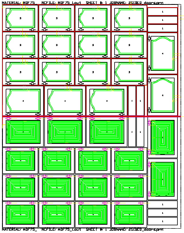
In this scenario, the bottom sheet has all the glass pockets, hinge hardware cuts, etc. that will be necessary on the backside. Then there is a reference cut made on the top and top left corner of the sheet. Next the sheet can be flipped over with the reference point being placed against the location pins. Then all the parts can have the details cut and then the profiles can be cut, releasing the part from the sheet. In this case, Common Line cutting could also be used on the top to reduce the cycle time necessary to release the parts from the sheet.
Operation
The general rules to this method are that all the geometry for the part (front and backside) must be in one drawing and on separate layers that can be controlled with a layer to knowledge association in the DOIT files.
In the drawing shown above, the red geometry is cut on the front side of the sheet and the blue geometry is cut on the backside of the sheet. Both front and back geometry must exist in the same drawing, DXF, or macro file.
The front and or back geometry can have negative thickness. If you want your knowledge to cut to the geometry thickness, then your total cut depth can either be left blank, or have a capital A, or a backslash and a value. Blank or A will make the cut depth to the geometry thickness. A backslash and a value will cut that value more or less than the geometry thickness:
This example will cut .005 MORE than the geometry thickness. If the geometry is -.75 thick, the cut depth will be -.755
This example will cut .125 LESS than the geometry thickness. If the geometry is -.75 thick, the cut depth will be -.625
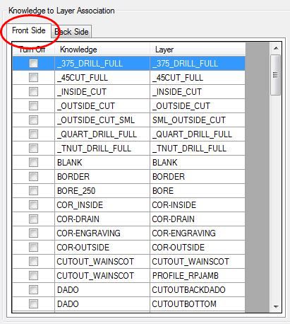
In the DOIT editor, there are two tabs. One for cuts on the first side and one for cuts on the second side. The order of these are as follows; The Backside tab is for the cuts that will happen first, before the sheet is turned over. The Front Side tab is for the cuts that will happen when the sheet is flipped over, containing all the cuts that will happen last and when the parts are cut loose from the sheet.
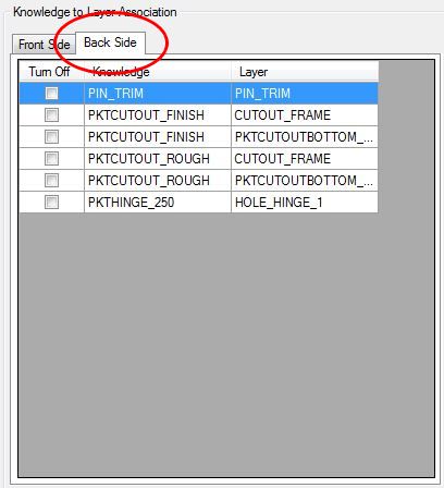
If you want to cut half way through on the front, and half way through on the back, then you need a knowledge and layer association that cuts half way through for both the Normal tab and another (or the same) knowledge association for the After Nest tab. If you want to cut all the way through on the front side, then that knowledge / layer association should be done in the Normal machining tab.
Note: You would never cut all the way through on the Backside because that would separate all the parts and you could not flip the sheet over!
Once you make the associations in these two lists, save the DOIT file.
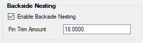
The Automated Two-Side Nesting is activated by checking the box in the Advanced Nesting tab that says 'Enable Backside Nesting'.
The vertical spacing needs to be set at 2.5 or more. This ensures that there is enough room to mirror the sheets.
For more information on changing the vertical spacing, refer to the Nesting section.
Note that Automated Two-Side Nesting requires rectangular stock only, irregular stock shapes with more than 4 sides will not be mirrored.
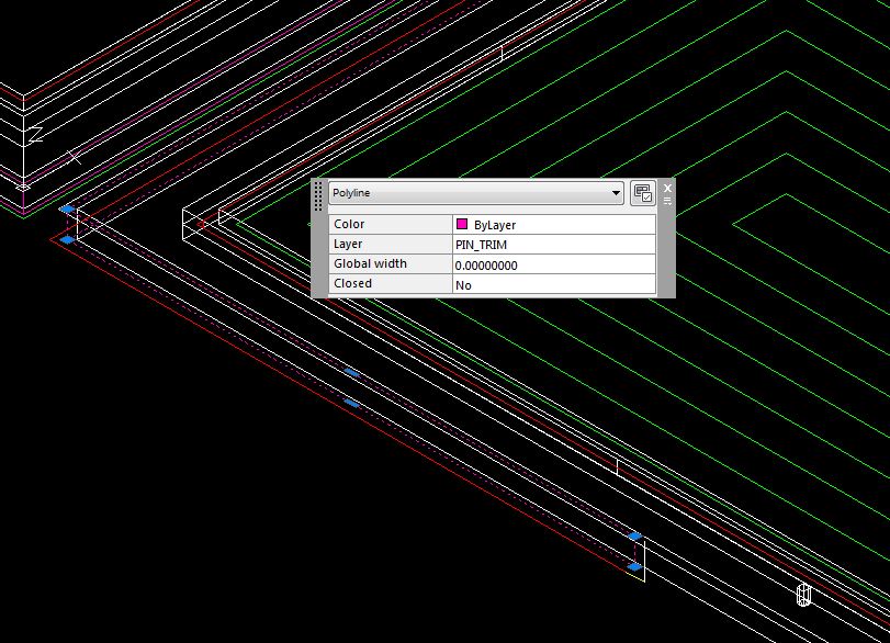
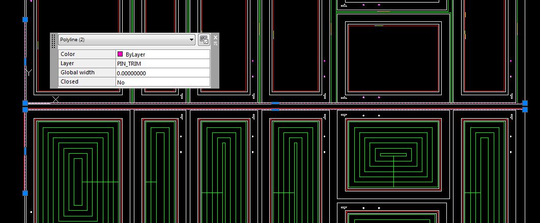
Pin Trim Cut
A trim cut is made along the edge of the backside sheet. This trim cut ensures a good edge to place up on the pop up pins when the sheet gets flipped over.
Router-CIM Automation Suite automatically makes geometry on layer pin_trim. You need a knowledge named pin_trim associated to layer pin_trim in the after nest DOIT file.
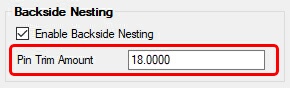
The pin trim geometry will be all the way on the X axis and 18.0 units in the Y axis. This can be adjusted by changing the 'Pin Trim Amount' value:
If you need a different knowledge for each material in your job, you can make a layer / knowledge association formatted like this:
Knowledge name: MATERIAL CODE+PIN_TRIM
Layer name: MATERIAL CODE+PIN_TRIM
As an example, The ¾ MDF material has a material code of 75MDF and the pin trim cut on this material will use a knowledge called 75MDFPIN_TRIM and the pin trim geometry will be on a layer called 75MDFPIN_TRIM.
Note: pin_trim Knowledge: This will be a Right-Hand (RH) Cut set to offset by the tool radius, cut to the RH and CCW direction. This is based on lower left Sheet Origin being selected. A different sheet origin may require a different cycle such as Left-Hand (LH) Cut.
The pin_trim geometry is offset by ½ of the edge allowance and will be shaved off the backside of the sheet and the origin of the main NC code file will be shifted by that amount. To change the default offset, please go to the 'Comman NCVARs in Automation' section.
The spacing between the front side nest and backside nest is defaulted to the bottom edge allowance defined in the material. If you want to adjust the spacing between the front side nest and backside nest in the nested DWG that is produced, please go to the 'Common NCVARs in Automation' section.
Results
When the job is run, the results will have two NC Code files for each sheet.
The regular sheet name and one with PRE in the name. The PRE is the backside and it is run first.
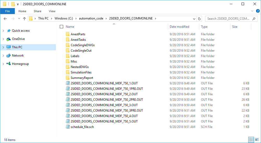
Schedule file
The schedule file will be created with the files listed in the proper order to be executed.
1,2SIDED_DOORS_COMMONLINE_MDF_750_1PRE.OUT,1,1,00:00:00,00:00:00
1,2SIDED_DOORS_COMMONLINE_MDF_750_1.OUT,1,1,00:00:00,00:00:00
2,2SIDED_DOORS_COMMONLINE_MDF_750_2PRE.OUT,1,1,00:00:00,00:00:00
2,2SIDED_DOORS_COMMONLINE_MDF_750_2.OUT,1,1,00:00:00,00:00:00
3,2SIDED_DOORS_COMMONLINE_MDF_750_3PRE.OUT,1,1,00:00:00,00:00:00
3,2SIDED_DOORS_COMMONLINE_MDF_750_3.OUT,1,1,00:00:00,00:00:00
4,2SIDED_DOORS_COMMONLINE_MDF_750_4.OUT,1,1,00:00:00,00:00:00
5,2SIDED_DOORS_COMMONLINE_MDF_750_5.OUT,1,1,00:00:00,00:00:00