DOIT File
Router-CIM Automation Suite runs on the drawing Layer to Cut Knowledge association principle. That means that for each Layer in a drawing that has geometry that you want cut on the machine, a Cut Knowledge must exist. Further, the two of them must be associated together in the system to allow Router-CIM Automation Suite to know that the partnership exists. From this area you may select a DOIT file (that is a Layer/Knowledge Association file) from the list of available DOIT files in the \Router-CIM\Automation\Doitdir folder. You can edit the selected file and add/remove associations, and even create new DOIT files for use in Router-CIM Automation Suite.
New DOIT File
In order to set up your layer-to-knowledge associations within a DOIT file, you need to create a DOIT file. The 'New' button should be used. Make sure that you save the DOIT file you created in the proper location so that Router-CIM Automation Suite will know where it is located. The location that Router-CIM Automation Suite goes to is defined in under File/Settings under the tab 'System Folders'.
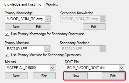
Edit DOIT File
Once a DOIT file is created or you need to make changes to an existing DOIT file, you need to select the 'Edit' button.
Once you select the 'Edit' button, the DOIT file editor will open.
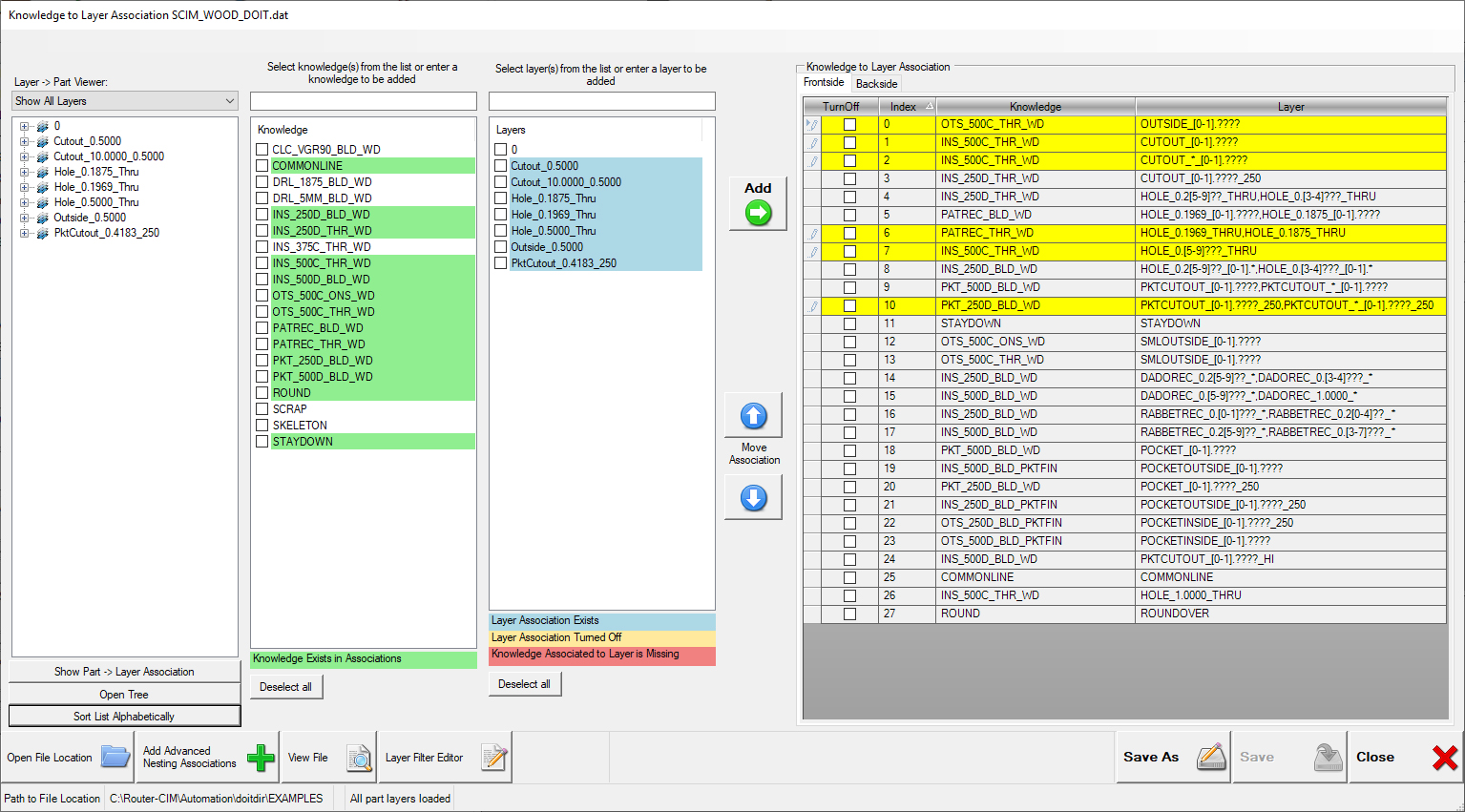
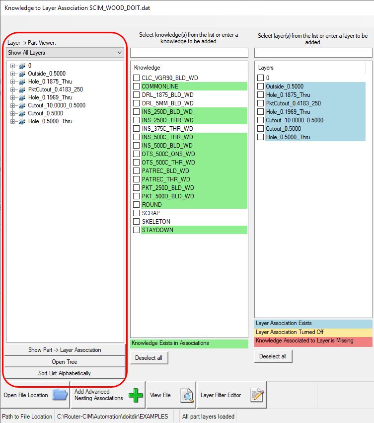
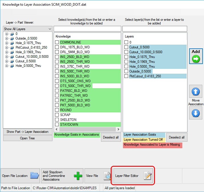
The DOIT file editor will search your currently selected knowledge drawing and the parts that included in the currently selected job. On the left hand side you will see three columns, Layer to Part Viewer, Knowledge and Layers. These columns represent the result of the search that was completed by Router-CIM Automation Suite so you will be able to see what knowledges are available to you, what layers are present in the job's drawings and which layers are on which parts.
The color assigned to a knowledge or layer represents one of the following. If the Layer is not a specified color, then no association to the layer exists and Router-CIM Automation Suite will not apply any cut knowledges to that layer.
Knowledge to Layer Association Color Definitions:
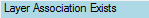
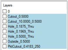
When you see the layer found by the DOIT file in the BLUE color, this means that in the DOIT file itself, there is an association to a cut knowledge that IS present in the Knowledge drawing:
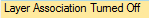
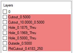
When you see the layer found by the DOIT file in the YELLOW color, this means that in the DOIT file itself, there is an association to a cut knowledge that IS present BUT the association is Turned Off:
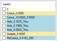

When you see the layer found by the DOIT file in the RED color, this means that in the DOIT file itself, there is an association to a cut knowledge that IS NOT present:

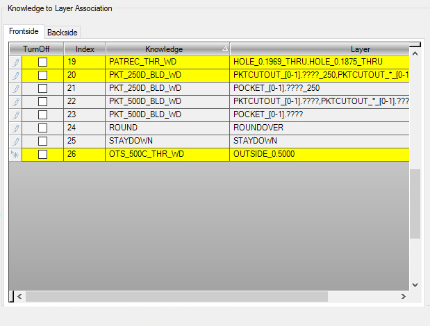
In the DOIT file shown on the right side of the DOIT Editor, associations that are being used in the current job will be marked in bright YELLOW:
Creating a Knowledge to Layer Association
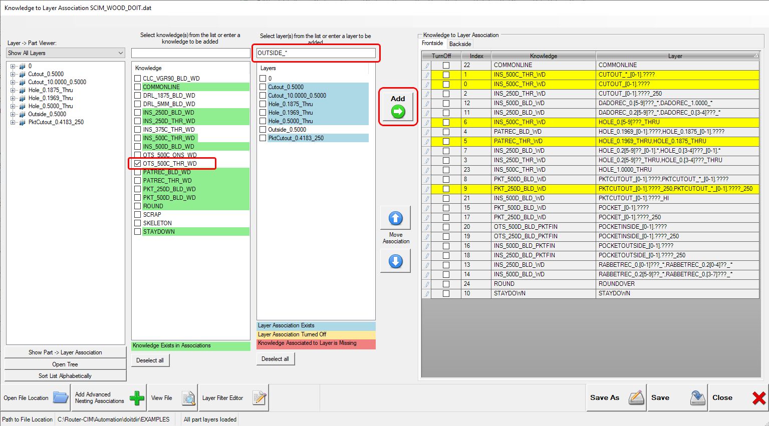
In the below example, you can see that layer 'OUTSIDE_0.5000' does not have a knowledge associated with it. In order to make an association, you will need to select the correct knowledge that will be used to machine the layer. If you do not have a knowledge created for this layer, please go to 'Edit Knowledge Drawing' for information on how to add a knowledge.
Note: The knowledge does not have to be named exactly the same as the layer.
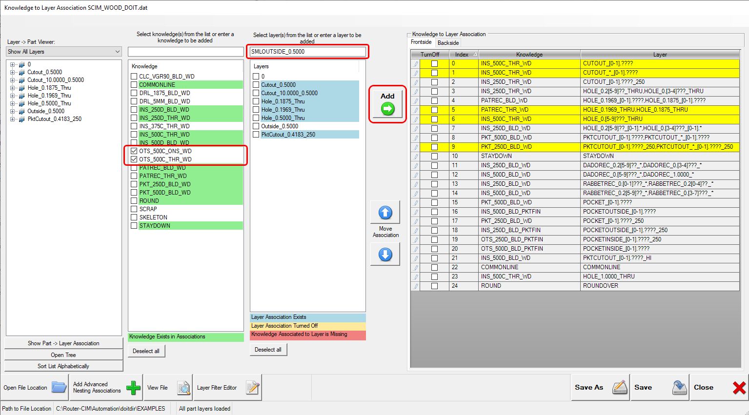
To make the association, select the correct cut knowledge and the correct layer on the left hand side of the window by selecting the check box.

Note: You can select multiple knowledges to associate with one layer or one knowledge to associate with multiple layers. Layers and Knowledges can be used more than one time.
Once you have selected the correct knowledge and layer, select the 'Add' button.
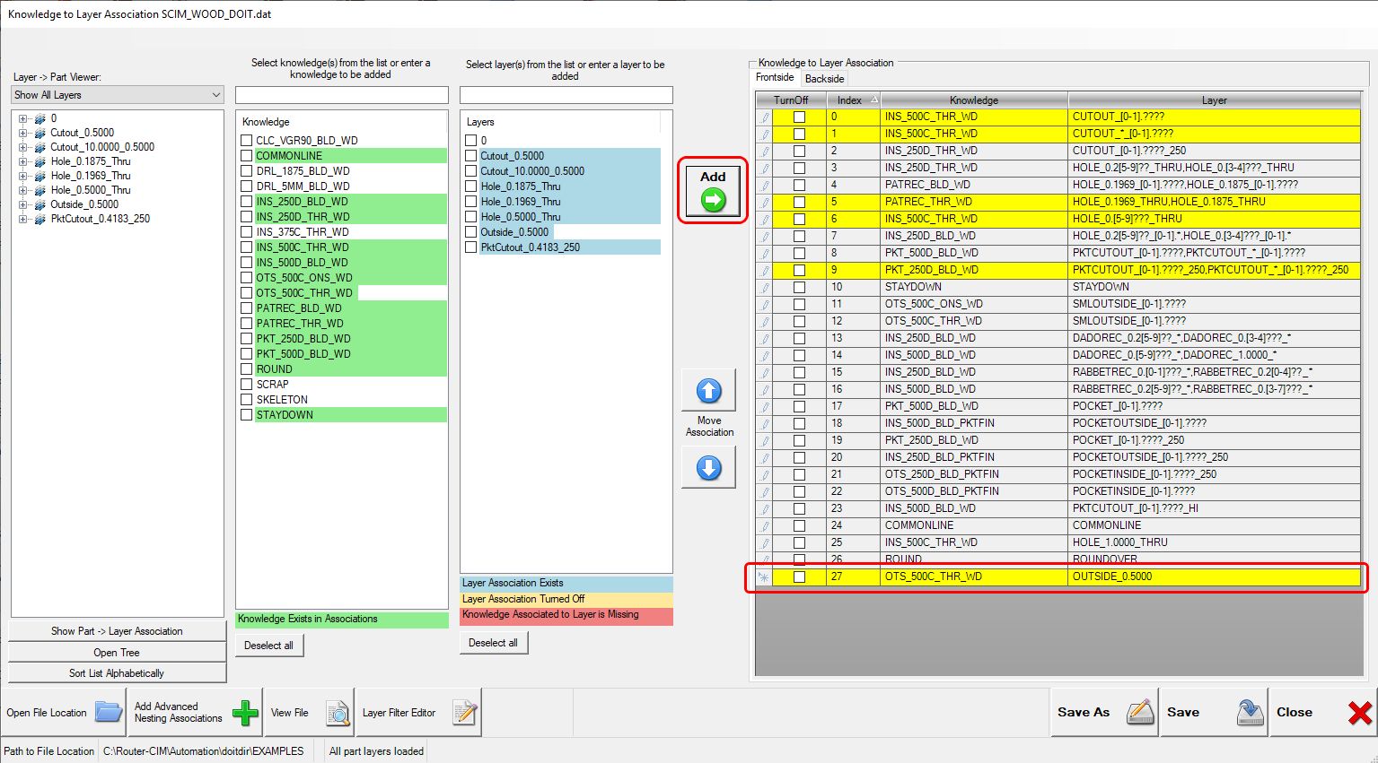
Once you select 'Add', you can see that the knowledge "OTS_500C_THR_WD" is now associated with layer "OUTSIDE_0.5000". This will mean that every time Router-CIM Automation Suite sees the layer "OUTSIDE_0.5000" it will use the cutting parameters defined in the knowledge "OTS_500C_THR_WD".
You can also manually type in cut knowledge names and layer names. This is common for SML associations when using the 'Rename Outside Layers' feature of Router-CIM Automation Suite.
When a cut knowledge is associated to a layer, the DOIT file editor will update the color definition automatically.
Creating a Knowledge to Layer Association using Wildcards
You can also use wildcards in order to make your Knowledge to Layer associations. The wildcard is a powerful tool that allows Router-CIM Automation Suite to use a knowledge on a layer that does not match exactly the layer name.
NOTE: Wildcards are a very powerful tool. They should be used with caution so that you do not have Router-CIM Automation Suite using cut knowledges for layers that you do not want to cut in that particular way.
Wildcards come in multiple different forms. Here is a list of acceptable options:
Wildcard
|
Description
|
*
|
The * (asterisk) is a way to ignore/discard any information that comes after it. An example would be if you were trying to associate the same knowledge to a layer called OUTSIDE_0.2500, OUTSIDE_0.5000 and OUTSIDE_0.7500, you could simply type in the layer text box OUTSIDE_0.* and associate this to the correct knowledge. As long as OUTSIDE_0. is at the beginning of the layer name, the rest of the layer name will be ignored.
|
Multiple *
|
You can also use multiple asterisks in order to filter out portions of a layer name. An example would be if you wanted to drill all holes that were any diameter from 0.2 to 0.29 and 0.5 inches deep with a 0.25 drill bit. If your layers included the diameter and depth, you may end up with many layers depending on how the circle was drawn. You can use multiple asterisks to accommodate this situation like HOLE_0.2*_0.5*. Associating your 0.25 drill knowledge to this layer would cover all circles drawn from 0.2 to 0.2999 and had depths of 0.5 to 0.5999.
To summarize, if multiple asterisks are used, the association will ignore what is after the first asterisk but then will need to see the continuation of the layer name if there is something present after it.
|
?
|
The ? (question mark) is defined as a single character. The difference here is that it does not ignore whats after it but only ignores a single character where the ? is found. An example would be if you are using a single digit as a trigger for something to happen. If I have a layer PKTCUTOUT_0.2501 where the final "1" represents picking a different tool. I could associate the correct knowledge to a layer like PKTCUTOUT_0.???1. This would mean that any pocket depth as long as there are 3 characters after the 0. and the fourth character would need to be a "1" in order for this association to happen.
|
[ ]
|
The [] will allow you to specify a range for a single character. An example would be to associate one knowledge for layers that range from DADOREC_0.2000_0.5000 to DADOREC_0.4999_0.2500 where you were not concerned about the depth.
The knowledge would be associated to a layer like this, DADOREC_0.[2-4][0-9][0-9][0-9]_*.
|
,
|
The , (comma) will allow you to associate one knowledge to multiple layers in one line of the DOIT file.
For example if I want the knowledge of OUTER_PROFILE to be associated to OUTSIDE_0.2500, OUTSIDE_0.5000 and OUTSIDE_0.7500, you would select the correct knowledge and type in to the text box above layers OUTSIDE_0.5000,OUTSIDE_0.7500,OUTSIDE_0.2500 and select the ADD button. This one association will cover all three of the layers.
|
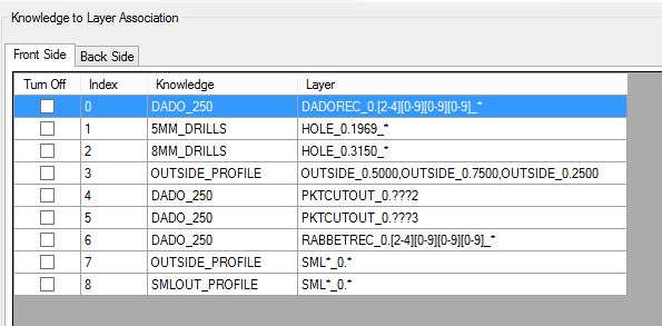
Here is an example DOIT file that shows some of the wildcard options:
To add a Wildcard association, please follow this procedure:
If I wanted to associate the knowledge "OUTSIDE_375" to all layers that begin with "OUTSIDE_", you would set up the association to as follows:
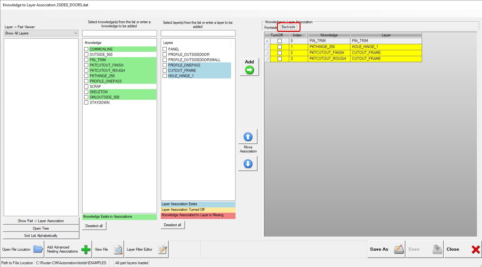
Adding Backside Associations
In order to use the advanced nesting module component "Enable Backside Nesting", you will need to complete the same process for layers that you want to machine on the backside of the part by selecting the "Backside" tab on the right side and repeating the process for all the backside operations. See 'Automated Two-Side Nesting' for more information.
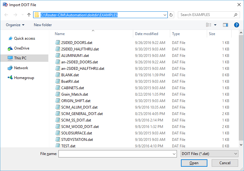
By selecting the 'Open File Location', it will open a windows browser showing you where your DOIT file is located. The file type will be a .DAT extension.
By selecting the 'Add Advanced Nesting Associations' button, Router-CIM Automation Suite will search your knowledges to find the STAYDOWN, COMMONLINE, SKELETON and PIN_TRIM knowledges and automatically create the layer-to-knowledge association. This button also works if your STAYDOWN, COMMONLINE, SKELETON and PIN_TRIM knowledges begin with the Material Code.
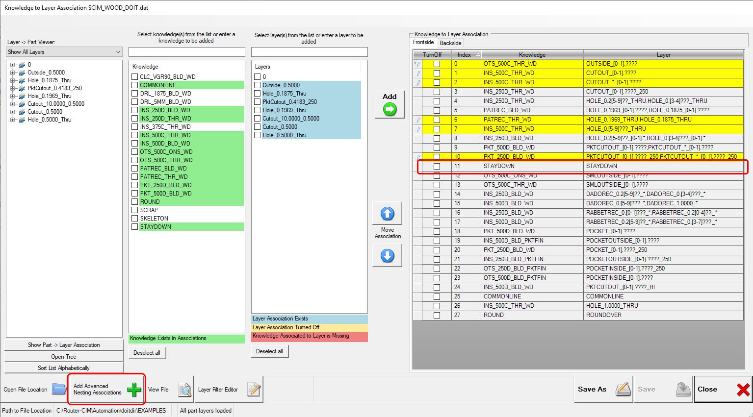
Note: For more information about creating Staydown and Commonline knowledges, refer to the 'Nesting Bridge Parameters' section.
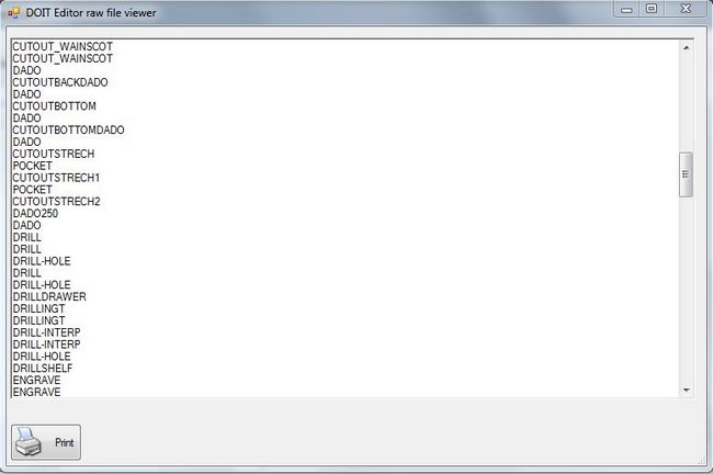
The 'View File' button will open the DOIT file in the raw format for reference.
After you have made the changes to the DOIT file, you can 'Save' the file or use the 'Save As' in order to give it a new name. The file must be saved in order to have Router-CIM Automation Suite use the layer-to-knowledge associations that you have defined.
Once the file is saved, you can select the 'Close' button.
Using the Layer to Part/Part to Layer Viewer
The Layer to Part/Part to Layer Viewer allows you to see either the Layers that the DOIT file found or the parts that are in the current job when the DOIT file was opened.
Show Layer to Part: This will show which parts the DOIT Editor found using the selected layer
Show Part to Layer: This will show which layers the DOIT Editor found in that particular part
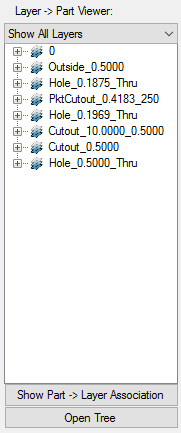
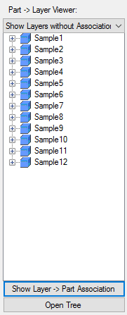
You can switch between the two options by selecting the Show Part -> Layer Association or Show Layer -> Part Association.
Layer to Part Association: Part to Layer Association:
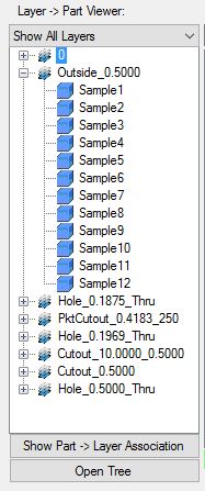
Each line will have an expand option shown as the '+' symbol. When selected, the selected line will expand showing you more details:
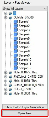
The 'Open Tree' button will expand all the '+' symbols with one click:
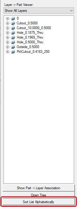
The 'Sort List Alphabetically' button will sort the layers for simple viewing:
You can decide what you want to see in the Layer to Part Viewer by using one of the sorting options:
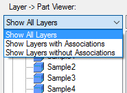
Show All Layers: Shows all the layers that the DOIT Editor found
Show Layers with Associations: Shows all the layers that the DOIT Editor found that had cut knowledges assigned
Show Layers without Associations: Shows all the layers that the DOIT Editor found that did not have cut knowledges assigned
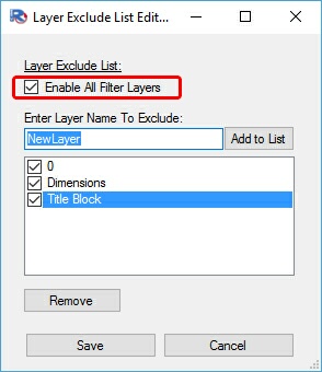
Using the Layer Filter Editor:
The Layer Filter Editor allows you to filter some of the layers that appear in the Layer to Part Viewer. This is common for AutoCAD default layers or layers that you may use in your drawings that are not relevant to Router-CIM Automation Suite. These layers may include things such as Dimension layers or Title Block layers, etc. The Layer Filter Editor allows you to only see the layers that you are interested in applying cut knowledges to.
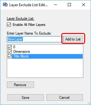
To Add A Layer to the Layer Filter Editor:
Simply type in the full layer name in the 'Enter Layer Name to Exclude' area and select the 'Add to List' button.
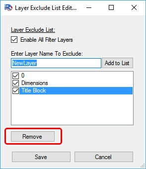
To Remove A Layer from the Layer Filter Editor:
Simply highlight the layer you want to remove and select the 'Remove' button.
Once your Layer Filter list has been completed, you will need to check the box by the layers that you want the Layer Filter Editor to exclude:
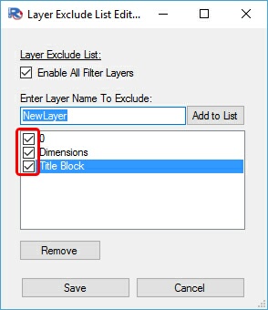
If you want to select all the layers, simply check the box for 'Enable All Filter Layers':