|
|

|

|
|||
|
|
|
|
Select the Nesting command from the icon or pulldown menu. The following will appear at the AutoCAD command prompt:
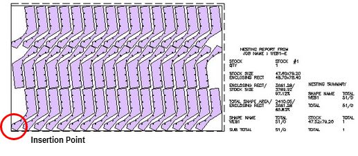
Insertion Pt <RETURN for (0,0)>:
Select a point (lower-left corner) where the nested layout will be placed.
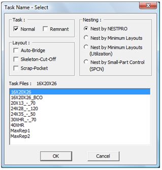
Subsequently, a dialog box as follows will appear.
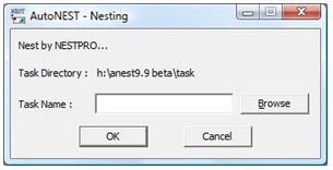
Task Directory |
Display the default task directory set at Sysdata. |
Task Name |
Enter the task name to be nested or click the
|
Task |
Referring to the pop-up window above, there are 2 selections : q Normal q Remnant “Normal” tasks refer to all task files (*.job) created by the user. “Remnant” tasks refer to tasks files (*.job) with the reserved suffix, “_$REM” . For example : XYZ_$REM.job. “Remnant” tasks are automatically created if the “Save Remnant” check-box in the Nesting Options of TaskEdit is marked. For more details, refer to TaskEdit. |
Nesting |
There are 4 nesting engines for selection. •NESTPRO •Minimum Layouts •Minimum Layouts (Utilization) •Small-Part Control (SPCN) The default is NESTPRO which is best suited for most jobs. However when the parts’quantities are high, it is recommended you use “Minimum Layouts (Utilization)” nesting engine. This engine is designed to optimize the utilization of the stocks as well as to achieve a high repeatability of the layouts, thus minimizing the number of different nested layouts. “Minimum Layouts” engine is only suitable when the stock materials are inexpensive and the objective is the maximize the repeatability of the nested layouts or cutting plan. “SPCN” is only suitable for cutting machines with un-uniform suction where certain areas have weak suction. Therefore small-parts should not be nested over such weak suction area(s). This new nesting engine will ensure small-parts are nested within the designated “Small-part Zone”. |
Layout |
There are two check-boxes : q Auto-Bridge q Skeleton-Cut-Off q Scrap Pocket Mark the ‘Auto-Bridge’ check-box if you wish to include bridging into the nested layouts. Similarly mark the ‘Skeleton-Cut-Off’ or “Scrap-Pocket” checkbox if you wish to include skeleton-cut-off’s or Scrap-Pockets into the nested layouts.
AutoBridge, Skeleton-Cut-Off and Scrap-Pocket will follow the specifications as defined in TaskEdit.
For more details, refer to TaskEdit. |
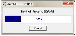
Once the Task name has been confirmed, click the OK button to start the nesting. The following dialog box appears – indicating that the nesting is in progress.
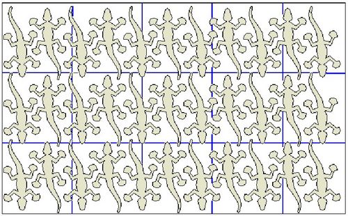
The nested layout will be displayed onto the current drawing, at the location indicated by the Insertion point.
Once a task has been successfully nested, output files will be created on the same folder as the Task. These files have the same name as the Task but different file extensions as shown below.
Example : Task name is SAMPLE
Output Files:
SAMPLE.SYM
SAMPLE.SUM
SAMPLE.XLS or XLSX
SAMPLE_SYM.XML
SAMPLE_SUM.XML
The .SYM file contains the results of the nesting in terms of each part and its location in the layout. The formats of above files are described in detail in SYM File Format section.
The .SUM file contains the nesting summary report in TEXT format.
The .XLS or .XLSX file is an Excel spreadsheet of the nesting summary.
The two .XML files contain the same information as .SYM and .SUM but written in extensible markup language (XML).
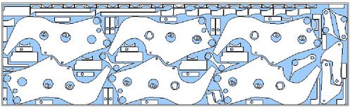
Nested Layout with Skeleton-Cut-Off: