|
|

|

|
|||
|
|
|
|
All the pertinent information of the nested results are in a file with the filename extension of .SYM. Assuming that the task name is example, it will therefore be example.sym.
The .SYM file is intended to be the standard vehicle for communicating with any other applications.
From AutoNEST V9.5.3 onwards, the .SYM file format has been changed to V9 REV1. (previously it was “V9”). See below :-
The format is as follows:
1 #
2 # AutoNEST V9
3 # Sym File Name = EXAMPLE.sym (REV1)
4 # Layout from NESTPRO.EXE
5 #
6 # Process Time Taken
7 #
8 # Input: 0 min 0.98 sec
9 # Pair I: 0 min 0.79 sec
10 # Pair II: 0 min 0.06 sec
11 # Packing: 0 min 0.18 sec
12 # Total: 0 min 2.03 sec
13 #
14 JOB = BIGPART
15 No of Distinct Shapes = 8
16 Total No of Shapes = 8
17 Total No of Stock Sheet = 3 0
18 Encl Rect = (15.000000 15.000000) (8883.888560 3018.000000)
19 Stock Sheet = (3048.000000 9144.000000) x 2 99.00
20 Sum of Area of Shapes = 18935546.178672
21 (BW4 1399.477698 717.433929 0.000000 5 0 1)
22 (BW3 7386.392422 2313.960112 0.000000 4 0 1)
23 Encl Rect = (15.000000 15.000000) (8830.763448 3018.000000)
24 Stock Sheet = (3048.000000 9144.000000) x 1 99.00
25 Sum of Area of Shapes = 22917695.314072
26 (BW2 1099.802730 2029.470929 180.000000 3 0 1)
27 (BW1 8067.357744 1106.283027 180.000000 2 0 1)
28 Encl Rect = (15.000000 15.000000) (7744.557323 3018.000000)
29 Stock Sheet = (3048.000000 9144.000000) x 1 99.00
30 Sum of Area of Shapes = 16455773.523961
31 (BW9 2244.239528 2501.755357 180.000000 3 0 1)
32 (BW8 2146.288772 607.457250 0.000000 2 0 1)
33 (BW5 5603.085323 2510.045662 0.000000 6 0 1)
34 (BW7 5663.686544 537.954338 180.000000 1 0 1)
(Note: The above line numbers are strictly for referencing purposes, they do not appear in the file.)
Description of .SYM File Format
Line 1 to 13 |
Lines start with "#" character denote comments. There is no limit to the number of comment lines. The 'AutoNEST V9’ must be in one of the comment lines. The ‘V9’ reference number is used to check the different formats of (.SYM) files for different software releases.
|
Line 14 |
Sym file name. The key character here is the "=" equal sign. The words before it are purely descriptive but the name after the sign is important.
|
Line 15 |
Number of distinct parts. The key character here is the "=" equal sign. The words before it are purely descriptive but the value after the sign is important.
|
Line 16 |
Total quantity of parts nested. The key character here is the "=" equal sign. The words before it are purely descriptive but the value after the sign is important.
|
Line 17 |
Total number of distinct nested layouts. The key character is the "=" equal sign. The words before it are purely descriptive but 2 values (separated by space) indicate the no. of distinct nested layouts for regular and irregular stocks respectively.
|
Line 18-22 |
The first nested layout information.
|
Line 18 |
Enclosing rectangle of the first nested layout. The first pair of real numbers is the left-bottom point of the rectangle, the second pair is the length and width of the rectangle.
|
Line 19 |
Stock sheet size and the number of the repeated layout and Cost per stock. Within brackets are the width and length of the stock.
The last number is the Cost per stock.
|
Line 20 |
Sum area of parts nested in the current layout.
|
Line 21-22 |
A list of nested parts. Each line has the following format: (Part-name X Y Angle Color Hole_no Layer)
Part name - name of the part (X, Y, Angle) - Position of the part, relative to the left bottom corner of the respective stock.
|
|
Color - indicate the color to be used on screen |
|
Hole-no - indicate which hole the current part is being nested as the Part may have multiple holes (these are differentiated by the “Hole no.” in .VEC file
‘0’ means the part is NOT inside any other part’s hole. ‘>0’ means the part is inside a certain hole no. of the part
|
|
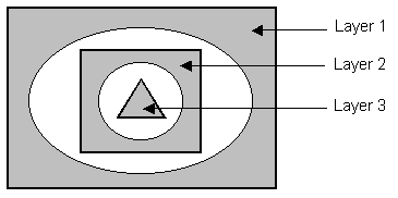
Layer - the meaning is different from the Drawing layers that most of us are familiar with. Here, it means whether a part is nested in multiple levels of “Part-In-Part”. The diagram below illustrates what it means to be called “Layer 1”, “Layer 2”, “Layer 3” and so on.
|
Line 23-34 |
The second and third nested layout information.
The part X/Y coordinates and the enclosing rectangle in the second layout are relative to the left bottom corner of the 2nd stock.
Similarly, the part X/Y coordinates and enclosing rectangle in third layout are relative to the left bottom corner of the 3rd stock and so on |
IMPORTANT: Do not use 'Tab' characters when you are constructing this file with a text editor or word processor. Instead use ordinary spaces.
An Irregular stock will have the following .SYM file format :-
1 #
2 # AutoNEST V9
3 # Sym File Name = IRREG-1.sym
4 # Layout from NESTPRO.EXE
5 #
6 # Process Time Taken
7 #
8 # Input: 0 min 0.08 sec
9 # Pair I: 0 min 0.68 sec
10 # Pair II: 0 min 0.02 sec
11 # Packing: 0 min 1.98 sec
12 # Total: 0 min 2.76 sec
13 #
14 JOB = IRREG-1
15 No of Distinct Shapes = 5
16 Total No of Shapes = 87
17 Total No of Stock Sheet = 0 3
18 Encl Rect = (0.000000 0.000000) (3806.703954 3258.750718)
19 Stock Sheet = (3258.750718 3806.703954) x 1
20 Stock Area = 9234599.16 Sum of area of shapes = 5673622.50
21 (&i-stk 2685.912593 1921.541344 0.0 1)
22 (17-1 3445.292074 1876.218412 11.766537 2 0 1)
23 (17-1 2854.195540 2200.574867 -168.233463 2 0 1)
24 (17-1 2163.516778 1875.891255 11.766537 2 0 1)
25 (17-1 1572.420244 2200.247710 -168.233463 2 0 1)
26 (17-1 418.622195 2774.246774 -269.985376 2 0 1)
27 (17-1 2566.064366 443.120389 -179.985376 2 0 1)
28 (17-1 2398.265618 961.253189 -179.985376 2 0 1)
29 (PART3 2117.604589 1421.560227 0.014624 3 0 1)
30 (PART3 2324.528435 1260.959391 180.014624 3 0 1)
31 (PART3 3624.289236 376.923330 267.808871 3 0 1)
32 (PART3 1849.929902 1349.789402 270.014624 3 0 1)
33 (PART3 2851.255095 1352.473314 180.014624 3 0 1)
34 (PART4 154.152797 3096.646617 270.000000 4 0 1)
35 (W19 994.017396 2813.313029 180.014624 5 0 1)
36 (W19 928.893289 1829.261109 0.014624 5 0 1)
The difference between regular stock and irregular stock are as follows :-
Line 19 |
Overall dimension of the irregular stock and the number of repeated layout(s). (Within brackets are the overall width and length)
|
Line 20 |
Area of irregular stock and Sum of area of parts nested in the current layout.
|
Line 21 |
List ir-stock name and position. The format for this line is: &ir-stock-name X Y Angle Color
‘&’ is a prefix to differentiate the irregular stock from the regular stock.ir-stock-name is the .STK file name of the ir-stock. X, Y, Angle - transformation of the ir-stock, relative to its enclosing rectangle’s left bottom point (0, 0).
In this current version the Angle is always 0.0. and the Color always 1.
|
Transformation of SYM File
IMPORTANT NOTES
From this version V9.5.3 onwards, there is a change in the SYM file. The ONLY difference between this new format and the previous is the X/Y co-ordinates reference point of transformation of the PARTS. This SYM format is named “V9 REV1”.
Under the new SYM format, each layout uses its own stock rectangle’s left-bottom point as the reference point or starting point, with the coordinate of (0,0). Each part’s X/Y data or co-ordinates in the SYM file is relative to its respective stock rectangle’s left-bottom point. (It is no longer relative to the first layout’s starting point – as in previous version) Under the new SYM format, Parts, Stock Sheets and Enclosing Rectangles are all transformed in the same way, through a set of ‘external or predefined settings’ in the ANEST.SET file, under the heading @LAYOUT. See below :
@LAYOUT
1.1 0 # Horz display ratio between layouts (0:based on individual stock length; 1:based on
longest stock length)
40 # Report length of layout summary
1.2 # Vert display ratio between rows (based on the biggest stock width)
0 # Max no. of layouts displayed per row (0:no limit)
1 # Location of layout summary (1:right; 2:top-left; 3:top-right)
For a detailed explanation of the settings in ANEST.SET, @LAYOUT, please refer to Chapter 7 pages ‘7-22’ – ‘7- 24.
See Page ‘6-25’for an illustration of the new .SYM file format (“V9 REV1”).
Parts Referencing
In the first nested layout, the X/Y co-ordinates of each part is relative to the Insert Pt (the left-bottom point of 1st stock). Insert Pt is obtained interactively through AutoCAD as one of the prompts during the Nesting command. If running in the Nest Manager environment (Windows), a default value of (0, 0) is taken, even though users can still set a different value in the ANEST.SET file.
To display the nested parts in the 2nd layout, users can predefine the offset distance from the first layout. By default, a distance of ‘1.1’ ratio of the Stock Length is used. This means the second layout is positioned at an offset distance of ‘1.1 x 1st Stock Length’.
(1.1x 1st Stock Length)
Users can change this ratio via the 1st parameter in @LAYOUT (ANEST.SET). If ‘Layout Summary Report’ is chosen to be displayed also, the offset distance from first layout to second will be :-
(1.1x 1st Stock Length) + (40 x Textsize of “Layout Summary report”)
where “1.1” & “40” are defined in @LAYOUT (ANEST.SET).
Textsize of “Layout Summary report” is defined in Sysdata (8th line in ANEST.ARG)
The same transformation rule applies to the display of the subsequent nested layouts.
Based on the above information, OEM Partners can make their nested layouts transformation according to their own application needs. Now the X/Y coordinates in the SYM file are all ‘absolute’ data (no offsets included) and the various offsets can be preset externally in ANEST.SET – thus making the work if any, easier for OEM Partners.
Stock Sheet Referencing
The first stock sheet (rectangle) is drawn or displayed from the left bottom – which is the Insert Pt. Subsequent stock sheets are drawn with the specified offset distance as set in @LAYOUT in ANEST.SET (refer to 1st and 3rd parameters)
Enclosing Rectangle Referencing
No change from the previous version.
Enclosing Rectangle is the minimum rectangle that encloses the nested parts within the stock. The enclosing rectangle coordinates in SYM file is in this format: (X Y) (Length Width), where (X Y) is the location of its left bottom point which is relative to the left bottom point of its respective stock sheet rectangle (not the original Insert Pt.). The transformation of the Enclosing Rectangle is the same as Stock Sheet and Nested Parts.
Repeated Layouts
No change from the previous version.
Note that in some cases, there can be repeated layouts, i.e. nesting patterns with identical arrangement of nested parts and quantities. In the SYM file, where there are “repeated layouts” it is indicated on the following lines (based on the .SYM file in page ‘6-18’):
19 Stock Sheet = (3048.000000 9144.000000) x 2 { 2 nos of identical layouts}
24 Stock Sheet = (3048.000000 9144.000000) x 1 { only 1}
29 Stock Sheet = (3048.000000 9144.000000) x 1 { only 1}