|
|

|

|
|||
|
|
|
|
During cut you will be prompted not only to select the surface or solid to cut, but for your flow lines as well.
Using the MCADFLOW.dwg file, select the XNURBS_CUT-FLOWCUT Cycle.
Select Slice Settings to be sure the Slice Vertical Angle is set to 0.0, and the Slice Mode is Zigzag.
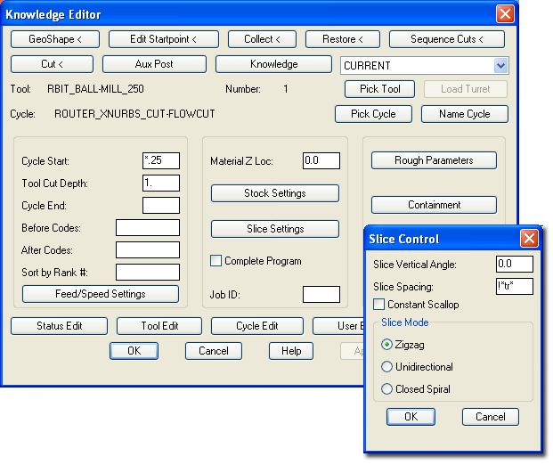
Press the 'Cut' Button.
The output of these settings should produce a tool path like this:

Slice Angle of 0.
Erase the previous tool path, then change the Slice Settings Vertical Angle to 90.0.
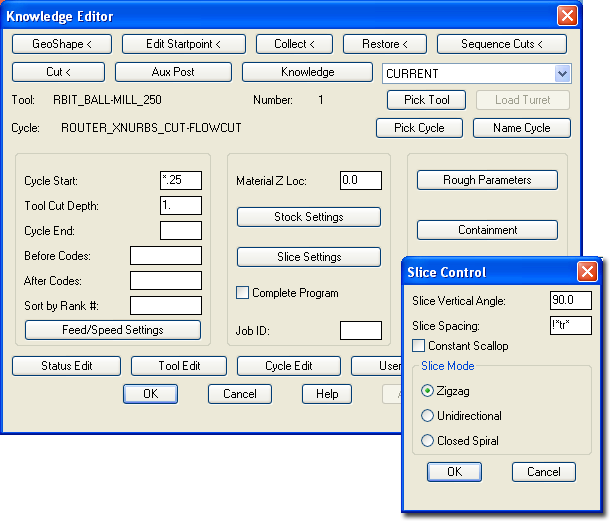
Press the 'Cut' Button.
The output of these settings should produce a tool path like this:

Slice Angle of 90.