|
|

|

|
|||
|
|
|
|
|
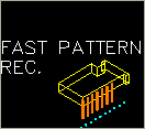
Fast Pattern Recognition is the same as regular Pattern Recognition, except that it substitutes fast feed moves for the rapid index moves between drills, which actually speeds up the overall drilling operations.
The Pattern Recognition cycle examines the drill holes on your part and the configuration of your drilling head(s) to determine the most efficient means of boring the selected holes. In order to use this function properly, the configuration of your drill heads must be set before you attempt to use this cycle. (See Note below.) Once configured, pick Pattern Recognition from the Cycle menu, choose Cut, and then select the holes to be bored. Pattern Recognition will load into memory, determine the most efficient route, and then proceed to bore the holes. The lead spindle in the group will have the tool path displayed on the screen; the others in the group will change colors to show they have been processed. The gang drill drawing will be provided to you by CIM-Tech following the specifications of your machine tool. Drill holes processed with Pattern Recognition need not be Geoshaped, and should be given thickness equal to their depth (negative Z value). |
NOTE: The size of the holes on your gang drill drawing in your machine-specific default drawing MUST BE THE SAME SIZE as the holes in your current drawing for Pattern Recognition to work. You do not need to add any tool numbers in the Control Panel, as Pattern Recognition will find the tools it needs and add them automatically.

Typical Pattern Recognition Part.

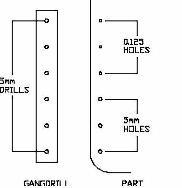
Match the drill block drawing to the drills in the machine.

Result of Pattern Recognition.
In the example above, the two rows of shelf holes are 32mm apart (1.2598") and there are two rows of 14 each. There are also two sets of hardware holes with sizes that do not match the shelf holes. With the drill block shown above, there are 7 drills in a row that match the shelf holes, so the drill block only drops twice on each row, drilling 7 holes each time. It then drills each of the hardware holes one at a time. In this instance, there are 10 drill cycles for a total of 34 holes.

Fast Pattern Recognition parameters.
Pattern Recognition - Tolerance Variable (*pat_fuzz*)
For Pattern Recognition to work properly, the diameter of the holes in your current drawing must be the same size as the holes on your gang drill drawing in your machine-specific default drawing (which is loaded into your current drawing upon loading Router-CIM). There is a tolerance built into the system, for the diameter of the holes, that is set to 0.05. This variable is *pat_fuzz* in the NCVARS. Under normal circumstances this need not be changed. But, if you have tools of a similar size (i.e. within .05 in radius or diameter) then Pattern Recognition may choose the wrong tools to complete its boring operation. Generally, if you are using all inch or all metric this will not be a problem.
Example: There are six drills on the gang drill with 5mm diameter drills in them. The part has both 5mm and 0.125 diameter holes in it. The difference between these two diameters is within the 0.05 tolerance, so Pattern Recognition will see them all as one size. Therefore, all six drills will drop and drill all six holes and all hole diameters will be 5mm, which is incorrect.
The following parameters effect the toolpath creation:
Specify here the fastest feedrate your machine can achieve in X and Y. This will be the feedrate used to move between holes and index out of the holes.
Valid answers are Y for yes, or N for no. If it is left blank, N is filled in.
Safety Plane
The safety plane is the location in the Z axis where the tool can retract to between cuts.
This should always be a value that places the cutter above the part to be cut as each tool change, or index move between cuts is going to start from this point.
Placing an asterisk ( * ) before the number specifies that this value is an absolute point above the part, where leaving this out determines the point to be incremental.
See the Safety Plane section for more information.
Depth Per Pass
This field allows multiple depths of Cut in a single tool path. By setting this number to a value less than the Total Depth of the Cut, you will have multiple passes in the material.
For example, if you have 1" thick material and need to take three passes to Cut through, you would set the Depth/Pass field at .4 (any number between .35 and .5 is valid) and the Total Depth at -1.0. The code generated will produce the first pass at -.4, the second at -.8 and the third pass at -1.0.
In most of the standard Router-CIM cycles the tool paths will ramp down between the Cuts.
Total Cut Depth
The Total Cut Depth is the depth you wish to Cut to, regardless of the number of passes made. It is usually put in as a negative number because Z0 is set at the top of the part. Router-CIM uses this number to calculate the Z axis moves for the Total Depth to Cut into the material. If the Depth/Pass field has a number smaller than this, Router-CIM calculates the number of passes necessary to reach this depth.
You may enable Router-CIM to calculate the depth automatically for you based on the thickness you give a part. To do this place "A" in the Total Cut Depth field, and if you have given you part thickness, Router-CIM will use that value for the Z depth. Remember to give your part negative thickness!
Also, when you give your parts negative thickness, you can use a forward slash (/) followed by a negative value (-.01 for example) in this field. Router-CIM will take the negative part thickness (-.75 for example), and the negative value following the slash and calculate the Total Cut Depth. In this case the part would be cut to -.76.
Feedrate
This field specifies the cutting maximum Feedrate in either inches per minute or millimeters per minute, depending on the mode you are programming in. See the chapter on Advanced Settings for information on how to program variable feed rates.
Spindle Speed
This field sets the spindle speed in rpm's (revolutions per minute). This is a modal field to many machine tools, so if you do not change this field for each Cut with the same spindle, you may only see the output for this setting once although you have made more than one Cut with the same spindle.
**Changing values in the cycle parameters may yield unexpected results with some settings or on some geometry. Examine the toolpath and NC Code carefully before running your machine tool if you change these default settings.