|
Deep Bore is a multiple pass drilling cycle that offers some flexibility with regards to peck increments, chip clearing, and changing feedrates during the cut cycle. Typically this cycle will start at the Safety Plane, drill down to the first peck depth, retract enough to break the chip and then bore to the next peck depth. There is a parameter setting for the Chip Clear Increment and Chip Break Height where the tool can retract to the clearance plane between pecks to remove chips from the hole. There are also parameters available to change the feedrate at a certain point during the cut and allowances to change the peck increment at a specific depth, as well as new chip break and chip clear increments.
This cut cycle is meant for drilling in very thick material or when the tool needs to be retracted several times to keep the chips from clogging the tool.
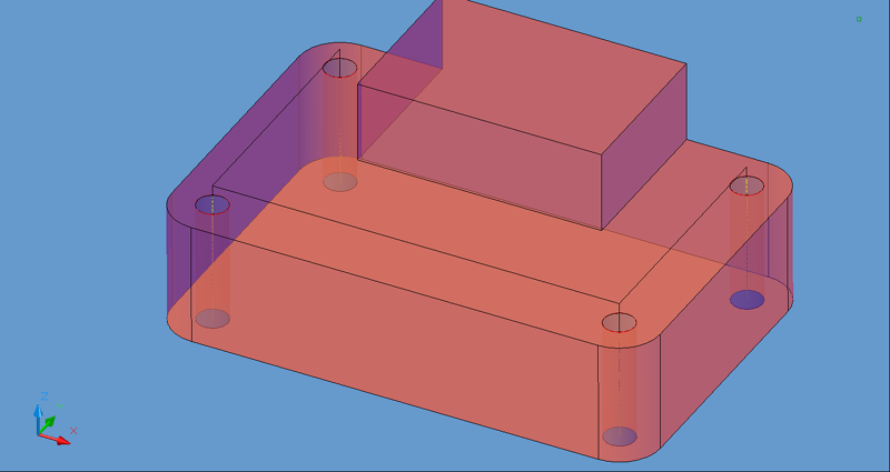
Holes drilled with this cycle should be grouped together like canned cycles so that each cut task can run on each hole. |

Deep Bore Cycle

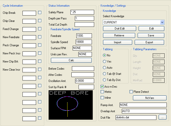
Deep Bore parameters.
The following parameters effect the toolpath creation:
How far to back up on a chip break move. A chip break move is usually a short motion to fracture the chip, and does not clear the hole.
Usually a multiple of the peck increment. When this secondary increment is passed, the drill is retracted to the clear plane.
Chip Break and Chip Clear work together making short strokes until the drill is loaded, then clearing the drill and starting over.
Entered as a depth in Z (typically negative). Change to a new feedrate when this depth is reached or passed.
New feedrate to change to when the Feed Change depth is reached or passed.
Depth to modify the Peck Increment, and chip handling values. Change to new pecking and chip handling values when this depth is reached or passed.
The value to use as the Peck Increment once the Peck Change depth is reached or passed.
The value to use as the Chip Break Height once the Peck Change depth is reached or passed.
The new Chip Clear Increment to use once the Peck Change depth is reached or passed.
The safety plane is the index plane Z location. If a ' * ' is used as the first character, that position is absolute in world Z coordinates, otherwise it is considered to be the distance above the shape.
This controls the depth per pass in Z. It is also the initial Peck Increment.
This parameter controls the total depth of the cut. If a '*' is used as the first character, that position is absolute in world Z coordinates. If it does not, then that distance is considered to be the distance below the initial shape.
Initial feedrate to start the drilling operation.
The RPM value to use for the spindle for this tool path.
Values placed here will be output in the cut cycle before the tool enters the material, typically at the height of the Safety Plane once the tool length compensation is set.
Values placed here will be output in the cut cycle after the tool has retracted from the cut, typically at the height of the Safety Plane after the cut is finished.
A numeric value to use for the tool path created to allow the Sequence to place cuts in a specific order when the code is created.
**Changing values in the cycle parameters may yield unexpected results with some settings or on some geometry. Examine the toolpath and NC Code carefully before running your machine tool if you change these default settings.