|
|

|

|
|||
|
|
|
|
Cabnetware integrates room and cabinet design capabilities with manufacturing tools. Cabnetware is for residential and commercial manufacturers of casework; allowing them to generate detailed drawings for use with building contractors and architects. This program has modules that allow it to export layered DXF files that can be imported into Router-CIM Automation Suite with the help of the Cabnetware import wizard.
Select the Cabnetware wizard from the list and you are presented with the following window.
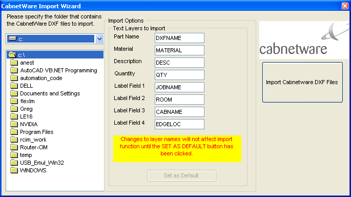
Select the folder where the DXF files are located on the left side. In the middle column you may edit the layers that the Cabnetware software presents it data on. Normally this is only done once and then left alone, however the option exists to change it should this be necessary.
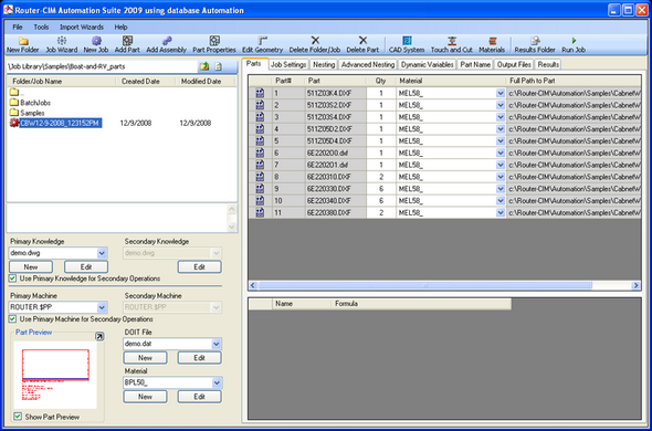
Once the folder containing the DXF files is selected, press the Import Cabnetware DXF Files button and a job will be added to the current folder.
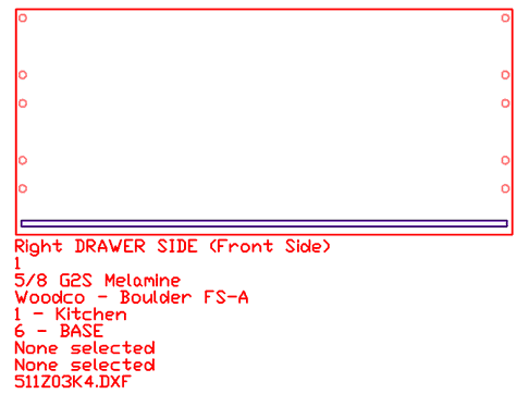
The Text Layers in Cabnetware DXF files contain information such as Material, Quantity, Job Name, DXF Name, etc... These are needed to process the parts through Router-CIM Automation Suite. The text is typically located in the lower left corner of the DXF.
Settings in Cabnetware
The following are the default layer names that should be used in Cabnetware.
| • | The outside of the part should always be placed on a layer that begins with BORDER |
| • | All vertical drill holes, regardless of size, should be placed on layer VBORE |
| • | Dadoes and rabbet's with a width of .25 inch should be placed on layer ROUTE 250 |
| • | Dadoes and rabbet's with a width of .375 inch should be rectangles on layer ROUTE 375 |
| • | Dadoes and rabbet's with a width of .500 inch should be rectangles on layer ROUTE 500 |
| • | Dadoes and rabbet's with a width of .625 inch should be rectangles on layer ROUTE 625 |
| • | Dadoes and rabbet's with a width of .750 inch should be rectangles on layer ROUTE 750 |
The following layers are for the text in each DXF file (Text height should be .125 and Text spacing should be .130).
| • | Part description should be placed on a layer called DESC |
| • | Part quantity should be placed on a layer called QTY |
| • | Part material should be placed on a layer called MATERIAL |
| • | Job name should be placed on a layer called JOBNAME |
| • | Room name should be placed on a layer called ROOM |
| • | Cabinet name should be placed on a layer called CABNAME |
| • | Edge band location should be placed on a layer called EDGELOC |
| • | Edge band material should be placed on a layer called EDGEMAT |
| • | DXF filename should be placed on a layer called DXNAME |
Layer |
Knowledge |
Tool |
Spindle# |
Border |
Border |
.5" Compression |
1 |
Vbore |
Vbore |
Multi Spindle Gang Drill |
Varies |
Route250 Route375 |
Dado250 |
.25 Router Bit |
2 |
Route500 Route625 Route750 |
Dado500 |
.5" Down Shear |
3 |
Table 1. Layer to Knowledge Association for Cabnetware Router-CIM
Cabnetware Notes:
In the Cabnetware "CNCAPP.INI" file the following should be set:
| • | Reverse Panel Reference = Y |
| • | Reverse Verticals Reference = Y |
| • | Output DXF Rects = Y |
To access the "CNCAPP.INI," in the Cabnetware CNC Link, go to "Help" pull down menu and select "About Cabnetware CNC" and then click on the purple disk icon to edit the INI file.
All geometry that is to be cut in like fashion (same tool, spindle, feed rate etc.) should be placed on the same layer.
Typically, dadoes and rabbet's should be output as rectangles that overlap the edge of the material by one tool radius (if the cut is to extend to the edge of the part.
All geometry should be output with negative thickness indicating cut depth.
Backside Parts with Cabnetware
There is a provision in Cabnetware to identify the parts which have backside or secondary operations. Likewise in Router-CIM Automation Suite there is a similar provision.
The parts which have DXF names that end in 1, 3, 5 are all treated as backside parts. When Router-CIM Automation Suite reads them in, it determines that last character and sets the job up to cut that as a separate part from the nested parts. It is likely in these types of jobs to have the same part name, except for the last character. The one that ends in zero ( 0 ) for instance will be nested and the one that has a 1, 3 or 5 will be cut as a single operation.