|
|

|

|
|||
|
|
|
|
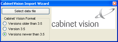
Cabinet Vision is a Planit Solutions cabinet design and manufacturing program. This program has modules that allow it to export layered DXF files that can be imported into Router-CIM Automation Suite with the help of the Cabinet Vision import wizard.
After making a job in Cabinet Vision, select the Cabinet Vision Import Wizard. You can select the format that matches the version of your Cabinet Vision software.
A window will appear allowing you to select the data file that was produced along with the layered DXF files.
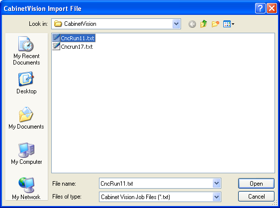
Select the Cncrun file for the job you wish to run and click Open. The files will be imported into Router-CIM Automation Suite in the current Jobs folder. The Cncrun file contains all the data for the job relating to the parts, materials, quantities and label information.
Settings for Cabinet Vision
The following are the default layer names that should be used in Cabinet Vision.
| • | The outside of a part should always be placed on a layer that begins with PANEL |
| • | All vertical drill holes, regardless of size, should be placed on layer DRILL |
| • | The Board layer should be placed on a layer that begins with BOARD |
| • | Dadoes and rabbets with a width of .25 inch should be rectangles on layer ROUTE 250 |
| • | Dadoes and rabbets with a width of .375 inch should be rectangles on layer ROUTE 375 |
| • | Dadoes and rabbets with a width of .500 inch should be rectangles on layer ROUTE 500 |
| • | Dadoes and rabbets with a width of .625 inch should be rectangles on layer ROUTE 625 |
| • | Dadoes and rabbets with a width of .750 inch should be rectangles on layer ROUTE 750 |
Layer |
Knowledge |
Tool |
Spindle# |
Panel |
Panel |
.5" Compression |
1 |
Drill |
Drill |
Multi Spindle Gang Drill |
Varies |
Route250 Route375 |
Dado 250 |
.25 Router Bit |
2 |
Route500 Route625 Route750 |
Dado 500 |
.5" Down Shear |
3 |
Table 1. Layer to Knowledge Associations for Cabinet Vision Router-CIM
Cabinet Vision Notes:
All geometry that is to be cut in a like fashion (same tool, spindle, feedrate, etc.) should be placed on the same layer.
Typically, dadoes and rabbets should be output as rectangles that overlap the edge of the material by one tool radius (if the cut is to extend to the edge of the part).
All geometry should be output with negative thickness indicating cut depth.
Backside Parts with Cabinet Vision:
There is a provision in Cabinet Vision to identify the parts which have backside or secondary operations. Likewise in Router-CIM Automation Suite there is a similar provision to cut them apart from the nested parts.
The parts which have DXF names that include an "F" as the fourth character are all entered as two parts automatically by the system, one which has the "F" in the fourth position, and one that has a "B" in the fourth position. When Router-CIM Automation Suite reads them in, it determines that identifying character and sets the job up to cut the "B" part as a separate part from the nested parts. It is expected that the Job Editor will have both parts in it when the import is complete, but the "B" part will not appear in the cncrun.txt file. If you then select the "B" part, you will notice in its properties that it has the flag set to be cut as a single operation.
If the "B" part exists in the Cncrun file, then you will see three parts with similar names, as the system automatically loads the "B" part when the "F" part is present. If it encounters a "B" part in the list, Router-CIM Automation Suite will treat that as another part in the job, which likely will be incorrect.