|
|

|

|
|||
|
|
|
|
Select the Nesting command from the icon or pulldown menu. The following will appear at the AutoCAD command prompt:
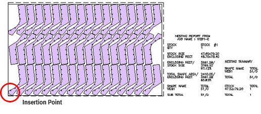
Insertion Pt <RETURN for (0,0)>:
Select a point (lower-left corner) where the nested layout will be placed.
Subsequently, a dialog box as follows will appear.
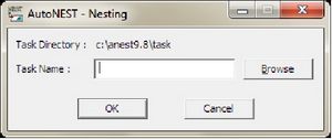
Task Directory |
Display the default task directory set at Sysdata. |
Task Name |
Enter the task name to be nested or click the
|
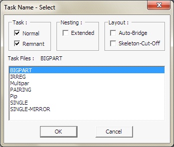
Task |
Referring to the pop-up window above, there are 2 selections : q Normal q Remnant “Normal” tasks refer to all task files (*.job) created by the user. “Remnant” tasks refer to tasks files (*.job) with the reserved suffix, “_$REM” . For example : XYZ_$REM.job. “Remnant” tasks are automatically created if the “Save Remnant” check-box in the Nesting Options of TaskEdit is marked. For more details, refer to TaskEdit. |
Nesting |
By default, the ‘Extended’ check-box is un-marked which means that the nesting will run its usual course. If the ‘Extended’ check-box is marked, then the nesting time is going to be longer as the nesting algorithms will run through an additional set of routines, compare with the original and then display the better of the two results. By running the Extended nesting, you will get either the SAME or BETTER nested results than if you were to run without marking the check-box. But there is a trade-off, Extended nesting will take significantly longer time to run. |
Layout |
There are two check-boxes : q Auto-Bridge q Skeleton-Cut-Off Mark the ‘Auto-Bridge’ check-box if you wish to include bridging into the nested layouts. Similarly mark the ‘Skeleton-Cut-Off’ check-box if you wish to include skeleton-cut-off’s into the nested layouts. Both AutoBridge and Skeleton-Cut-Off will follow the specifications as defined in TaskEdit. For more details, refer to TaskEdit. |
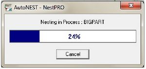
Once the Task name has been confirmed, click the OK button to start the nesting. The following dialog box appears – indicating that the nesting is in progress.
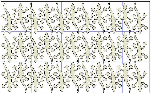
The nested layout will be displayed onto the current drawing, at the location indicated by the Insertion point.
Once a task has been successfully nested, output files will be created on the same folder as the Task. These files have the same name as the Task but different file extensions as shown below.
Example : Task name is SAMPLE
Output Files:
SAMPLE.SYM
SAMPLE.SUM
SAMPLE.XLS
SAMPLE_SYM.XML
SAMPLE_SUM.XML
The .SYM file contains the results of the nesting in terms of each part and its location in the layout. The formats of above files are described in detail in Chapter 6.
The .SUM file contains the nesting summary report in TEXT format.
The .XLS file is an Excel spreadsheet of the nesting summary.
The two .XML files contain the same information as .SYM and .SUM but written in extensible markup language (XML).
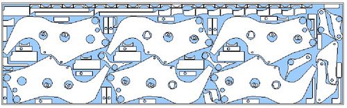
Nested Layout with Skeleton-Cut-Off: