|
|

|

|
|||
|
|
|
|
In TaskEdit., three (3) categories of information are required:
| • | Stock sheet (regular and irregular stocks accepted) |
| • | Parts to be nested |
| • | Cutting specifications |
| • | Bridge specifications (optional) |
| • | rectangular stocks of fixed size |
| • | irregular-shaped stock sheets |
| • | "coil" stock in rolls or reels. |
Select the TaskEdit. command either from the icon menu or the AutoNEST pulldown menu. The following dialog box will appear:
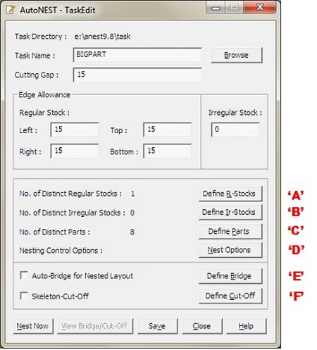
Explanation of the TaskEdit dialog box is given below:
Task Name |
Each task is given a user-specified name for future reference (.job). You can enter up to max. 31 characters (space and dot characters are not accepted).
Enter a new task name or click to select an existing task. You will see the Pop-Up Window below (left). Select the task file and click the “OK” button. Click the “Remnant” check-box and you will see the pop-up Window (below). Display in this list box are all task names with the suffix “_$REM”. You can change the existing specifications and save the new specifications into a new name or overwrite using the same task file name. |
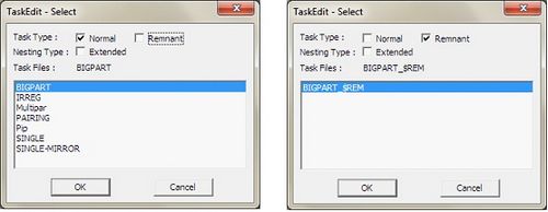
Task Type |
Referring to the pop-up windows below, there are 2 selections :-
‘Normal’ tasks refer to all task files (*.job) created by the user. ‘Remnant’ tasks refer to tasks files (*.job) with the reserved suffix, ‘_$REM’ . For example : XYZ_$REM.job. These tasks are created automatically when the ‘Save Remnant’ check-box is marked in the NEST OPTIONS of TaskEdit (“Nest Options” button is located at the lower-right corner of the dialog box). |
||||
Nesting Type |
By default, the ‘Extended’ check-box is un-marked which means that the nesting will run its usual course. If the ‘Extended’ check-box is marked, then the nesting time is going to be longer as the nesting algorithms will run through an additional set of routines, compare with the original and then display the better of the two results. By running the Extended nesting, you will get either the SAME or BETTER nested results than if you were to run without marking the check-box. But there is a trade-off, Extended nesting will take significantly longer time to run. |
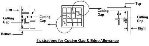
Cutting Gap |
This is the cutting gap between nested parts to allow for the tool size. |
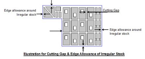
Edge Allowance -Regular Stock -Irregular Stock |
Sometimes, it is necessary to leave out an edge around the perimeter of the stock sheet. This is to cater for trimming or clamping purposes. For regular or rectangular stock, the edge allowance of the 4 sides of the stock can be defined. For irregular stock, a common edge allowance can also be defined. |
Left |
"Left" is the edge allowance of the regular stock in the x- direction from the left side of stock sheet. |
Bottom |
"Bottom" is the edge allowance of the regular stock in the y- direction from the bottom of the stock sheet. |
Right |
"Right" is the edge allowance in the x direction on the right side of the stock sheet. |
Top |
"Top" is the edge allowance in the y direction from the top of the stock sheet. |
No. of Distinct Regular Stocks |
Number of different sizes of stock sheets. (The maximum number of distinct regular stocks can be defined in ANEST.SYS under NEST@CONTROL) |
No. of Distinct Irregular Stocks |
Number of different sizes of irregular stock sheets. (The maximum number of distinct irregular stocks can be defined in ANEST.SYS under NEST@CONTROL) |
No. of Distinct Parts |
Number of distinct parts to be nested. A maximum of 1000 distinct parts is available for the current version. |
Define R-Stocks ‘A’
When you click the ![]() button, the following dialog box appears.
button, the following dialog box appears.
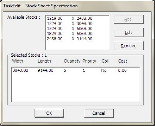
Width Length |
The width and length dimensions of the stock sheet. For 'Imperial Units' users, you can either enter in feet and inches or purely in inches. In the latter case, the inches will automatically be converted into feet and inches if Architectural-Imperial or Engineering-Imperial units are chosen. |
Quantity |
Quantity of stock-sheets of that particular size to be used in the task. Maximum quantity allowed for each distinct stock is 9999. |
Coil |
For stock sheets in reels or rolls, the length of the stock sheet can be extended beyond the specified dimension to accommodate the nesting results. If the ‘Coil’ check-box is marked, AutoNEST will have the liberty to increase the Length as much as it takes to pack all the parts optimally. |
Priority |
The priority of using the stock sheets when different stock sizes are available. You can define the order of priority in which AutoNEST should use the stock sheets. 1 has the highest priority. 99 has the lowest priority. If two or more stock sizes have the same priority number, the system will automatically decide based on the material utilization. To specify the PRIORITY between regular and irregular stocks, ‘Nest Options’à ‘Nest Regular Stock First’. |
Cost per Stock |
The cost per piece of Stock. |
Define IR-Stocks ‘B’
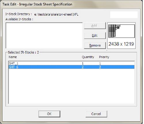
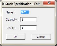

Name |
Show the name of the Irregular stock (.stk). If a list of irregular stock is selected, “$$$$$$$” will appear. |
Quantity |
Quantity of that particular irregular stock to be used in the task. Maximum quantity allowed for each distinct stock is 9999. |
Priority |
The priority of using the stock sheets when more than one is available. You can define the order of priority in which AutoNEST should use the Irregular stock. 1 has the highest priority. 99 has the lowest priority. If two or more stocks have the same priority number, the system will nest the smallest Irregular stock first. To specify the PRIORITY between regular and irregular stocks, see ‘Nest Options’à ‘Nest Regular Stock First’. |
Define Parts ‘C’
By clicking the ![]() button, the dialog box below appears:
button, the dialog box below appears:
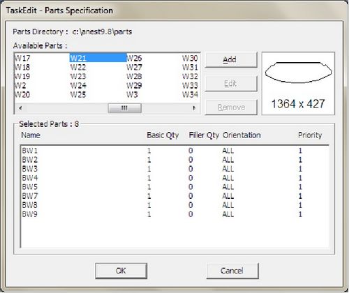
Whenever a part name from the listing of ‘Available Parts’ is highlighted, a viewer will display the part profile with the overall dimension of the part profile. The overall length and breadth dimensions will be rounded off to the nearest integer value.
Available Parts
Both the Add and Edit pop-up windows allow editing. The ![]() button will remove the part specification from the ‘Selected Parts’ list box. The
button will remove the part specification from the ‘Selected Parts’ list box. The ![]() button will place it back to the ‘Selected Parts’ list.
button will place it back to the ‘Selected Parts’ list.
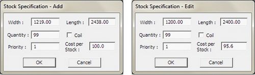
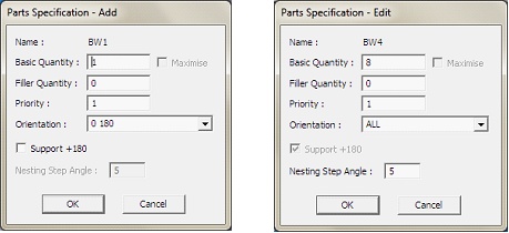
If you select the ![]() button the above pop-up windows will appear.
button the above pop-up windows will appear.
Explanation of the above dialog boxes is given below:
Name |
Show the name of the part that you have selected. If more than 1 part is selected, ‘$$$$$$$$’ will appear. |
Basic Quantity |
Number of that particular part required to be nested. Each part has a maximum quantity of 9999. |
Filler Quantity |
Numbers of that particular filler part to be nested. Each filler part has a maximum quantity of 9999. This is ‘optional’ quantity, to be used provided all the basic quantities have been nested and there is available space. AutoNEST will decide how many filler parts to be utilized in order to fill the stock to an acceptable layout. |
Maximize |
For single part tasks, mark the ‘Maximize’ check-box to specify ‘fill-up’ the whole stock sheet with the maximum quantity of parts. Not valid for coil stocks. |
Priority |
The priority of each and every part to be nested. 1 has the highest priority. 9999 has the lowest priority. AutoNEST will nest according to the priority settings i.e. parts of Priority 1 will be nested first, followed by Priority 2, then 3 and so on. If two or more parts have the same priority, AutoNEST will decide automatically which part is to be nested first. |
Orientation |
To allow for orientation constraints of the part during nesting. Format A 0 -- No rotation allowed. 0 90 -- 0� and 90� orientations allowed. 0 180 -- 0� and 180� orientations allowed. 0 90 180 -- 0�, 90� and 180� orientations allowed. ALL -- All orientations allowed. No orientation constraints.
Besides the above allowable orientations, you can specify any required angles of orientation (separated by SPACE). For examples :- 0 10 20 30 40 50 60 70 80 90 …. Format B This new format is helpful if the Orientation angles consist of a long list and if the angles increase by a constant value. (step 10 0 180) where: step is the reserved word to denote “increment angle”10 is the increment angle (must be greater than 0 and a positive value)0 is the Start Angle (real nos., range -360 ~ +360)180 is the End Angle (real nos., must be greater than Start Angle)If represented in Format A …. (0 10 20 30 40 50 60 70 80 90 100 110 120 130 140..….180) |
Support + 180 |
Mark the check-box, to allow the part to orientate to the specified angles and their +180� combinations. This option is not applicable when Orientation=ALL. |
Nesting Step Angle |
To allow a part to orientate step-incrementally in the defined angle during nesting. |
Click the ![]() command button to bring up the dialog box as shown:
command button to bring up the dialog box as shown:
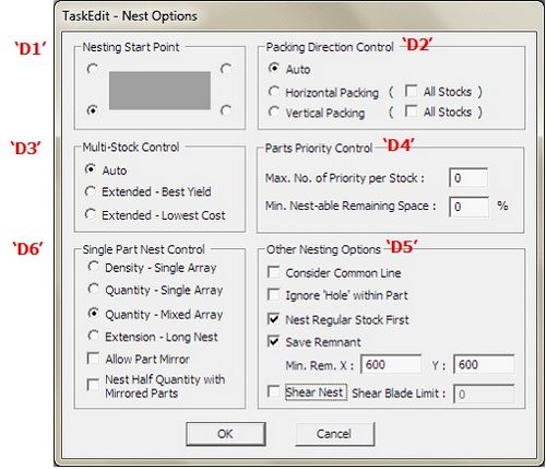
This dialog box allows the user to define control parameters for specific nesting output requirements.
The default settings are recommended for all users who do not require special nesting output conditions.
The options available are explained as follows:
Nesting Start Point
|
4 nesting start points are available depending on the user’s nested output requirements. Click one of the 4 corner points to set start point. Point chosen shall remain as default until it is changed. |
Packing Direction Control |
It is recommended for the packing direction to be set to ‘Auto’. However, if required either “Horizontal Packing” (pack along the x-axis) or “vertical packing (pack along the y-axis) can be selected. |
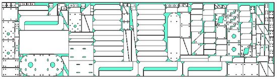
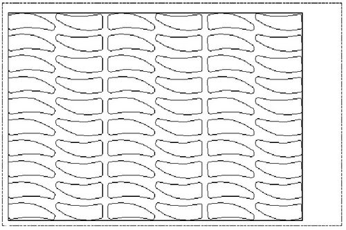
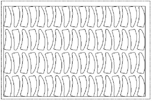
Auto |
AutoNEST will automatically decide the best packing direction based on the material utilization of the nesting. This is the default setting. See illustration below. |
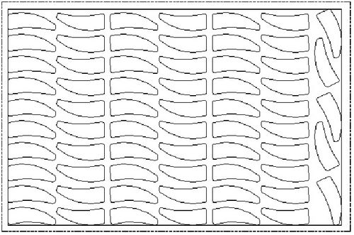
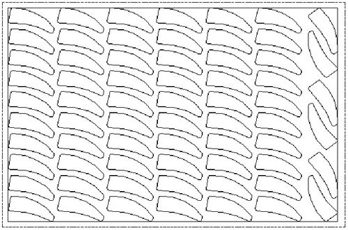
Horizontal Packing
|
When this radio button is marked, only the last nested layout will be packed horizontally. However, when the “All Stocks” check-box is marked, then all the nested layouts will be packed horizontally. See illustration below. |
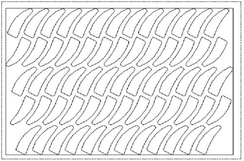
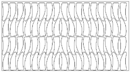
Vertical Packing |
When this radio button is marked, only the last nested layout will be packed vertically. However, when the “All Stocks” check-box is marked, then all the nested layouts will be packed vertically. See illustration below. |
Auto Packing:
Horizontal Packing:
Vertical Packing:
Multi-Stock Control |
There are 3 options available.
“Auto” is the default setting and is the fastest option where the nesting engine will appraise the parts and stocks and then automatically selects the largest suitable Stock to nest. “Best Yield” – in this option the nesting engine will iterate through each Stock size to nest the available parts. For each nested Stock, it will compare the nested utilization area of Stock and then select the one with the highest utilization. It will continue to iterate until all the parts or stocks are used up. “Lowest Cost” – in this option the nesting engine will iterate through each Stock size to nest the available parts. For each nested Stock, it will compare the Nested Area per Cost of Stock and then select the one with the highest Nested Area per unit cost. For this option to work, the “Cost per Stock” must be specified. Both the “Best Yield” and “Lowest Cost” will take a longer time to nest. ***The more the number of distinct Stocks, the longer it will take to nest for “Best Yield” or “Lowest Cost” options*** If either “Best Yield” or “Lowest Cost” option is selected, the Stock Priority will be ignored. |
Parts Priority Control
Max. No. of Priority per Stock |
This function works in conjunction with “Priority” of parts as defined in “Define Parts” ‘C’. There are 2 Parts Priority parameters to enable you to control the nesting of parts.
“Max. No. of Priority per Stock” enables you to limit the no. of Parts of different priorities to be nested into a stock. This is to avoid the confusion on the production floor where the operator, after cutting has to sort the parts and placed them into their respective “carts”. |
||||
Min. Nest-able Remaining Space % |
“Minimum Nest-able Remaining Space” percentage – is the parameter for the remaining space after ALL the parts of the specified Priority have been nested onto the stock. If 0 is defined, then any remaining space is considered “nest-able”, AutoNEST will try to find suitable parts to fit onto the remaining space. If 10 is defined, the remaining space must be >=10% of the stock size to be considered “nest-able”, AutoNEST will then try to find suitable parts to fit onto the remaining space. If 100 is defined, then any remaining space is considered NOT “nest-able”, AutoNEST will not attempt to nest into the remaining space after ALL parts of the specified priority have been nested. |
Other Nesting Options |
The nesting options are:
|
Consider Common Line |
Select this option if you want AutoNEST to consider packing of the parts along their common edges. This feature will save cutting time. However, AutoNEST will consider the common line packing together with the quality of the nesting. |
Ignore ‘Hole’ within Part |
Mark this check-box to ignore all “holes” and cut outs within Parts during nesting. So that no parts will be packed into these “holes” or cut-outs. |
Nest Regular Stock First |
Mark this check-box to nest regular stocks first. The default is to nest irregular stocks first. |
Save Remnant |
Mark this check-box to save the remnants of the stocks automatically after every nest, as long as they are of the minimum X and Y size or more. By default, the original profile of the rectangular stocks will also be saved with the remnants. However this can be changed in ANEST.SYS @REMNANT_CONTROL. By default these remnants will be saved into the Part/ Irregular Stock directory. The names of the remnant stocks will be Taskname_$REM1-1.stk, Taskname_$REM2-1.stk, Taskname_$REM2-2.stk and so on. The naming convention is as follows :- *_$REM(LAYOUT_NO)-(NO) where the suffix “$REM” can be defined in @REMNANT_CONTROL of ANEST.SYS. In addition, a Task will automatically be created bearing the name, Taskname_$REM.job. |
Min.Rem.X Min.Rem.Y |
The minimum remnant size as in the X and Y dimensions. The default dimension is 600 x 600. The maximum value is limited to 6 digits (Eg. 999999). |
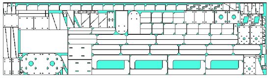
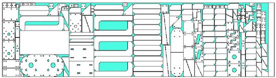
Shear Nest |
Mark this check-box to indicate “Shear Nesting” for that particular task. |
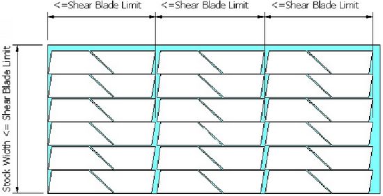
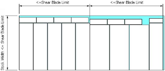
Shear Blade Limit |
When the ‘Shear Nest’ check-box is marked, you will be able to enter the ‘Shear Blade Limit’. See below. |
Single Part Nest Control |
This portion of the dialog box will be grey-out unless the Task consists of only ONE Part. For Single-part nesting, there are 6 options or controls. They are:-
The illustrations will give you a better understanding of these control settings |
||||||||||||
Density-Single array |
The most-dense packing pattern in a single array. |
||||||||||||
Quantity-Single array |
The highest quantity of parts nested in a single array. |
||||||||||||
Quantity-Mixed array |
This is the default option. Maximum quantity of parts nested onto the stock sheet. |
||||||||||||
Extension-Long Nest |
This nesting option will take the longest time compared with the other three. It will go through more iteration to produce either the same or better results than Quantity-Mixed array. |
||||||||||||
Allow Part Mirror |
If this option is checked, the nesting will consider the part (single) and its mirrored image during the nesting. However, it must be noted that checking this option does not mean that nesting will use the mirror counterpart of the single-part. Nesting’s main objective is to nest as many parts as possible and in so doing will try both the single part and its mirror counterpart to achieve that objective. “Allow Part Mirror” can be used in conjunction with any of the above 4 options |
Nest Half Quantity with Mirrored Parts |
If this option is marked, the nesting will nest half the defined quantity in the specified orientation and the other half in mirrored image of the first. If the quantity specified is “Maximize”, the nesting will half the stock in the specified orientation and the other half the mirrored image. If there is remaining space, again the same logic applies – half in 1 orientation and the other a mirrored image. “Allow Part Mirror” has no bearing on this option, by default half of the total parts nested will be the mirror image. |
Task Name : SAMPLE
Filenames : SAMPLE.JOB
SAMPLE_JOB.XML
Illustrations for Single Part Nest Control
Density - Single Array
Quantity - Single Array
Quantity - Mixed Array
Extension- Long Nest
Allow Part Mirror (coupled with the Quantity-Mixed Array option)
Nest Half Quantity with Mirrored Parts
Define Bridge ‘E’
By clicking the ![]() button, the dialog box below appears:
button, the dialog box below appears:
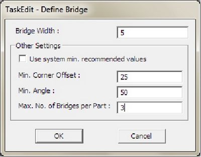
Bridge Width |
A “BRIDGE” is the narrow strip that links one Part to another in order to maintain a continuous cutting process. The width of the strip. Any numerical value is accepted, even zero. |
Other Settings Use system min. recommended values |
These are the other bridge specifications that you can define for the nested tasks. Mark this check-box if you want to use the minimum system default values which are :- Min. Corner Offset : 0.0 Min. Angle : 45 Max. No. of Bridges per Part : 5 |
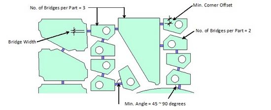
Min. Corner Offset |
The minimum distance to maintain from the edge of Bridge to the nearest corner. |
Min. Angle |
The angle formed by the Bridge and the part. The accepted range is 45 – 90 (degrees). See the following illustration. |
Max. No. of Bridges per Part |
The maximum number of bridges to be allowed to link to any one part. See the following illustration. |
Define Skeleton Cut-Off ‘F’
By clicking the button ![]() the dialog box below appears:
the dialog box below appears:
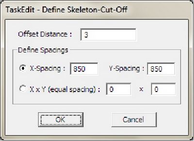
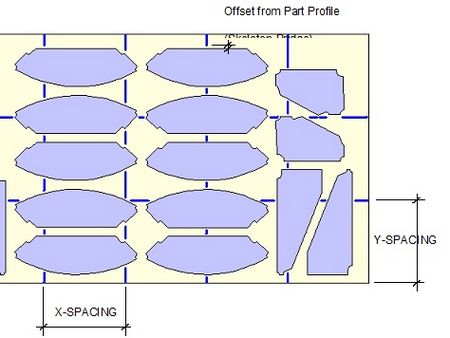
Offset Distance |
The gap between the skeleton-cut-off and the part profile (also called ‘skeleton-bridge’). |
X-Spacing, Y-Spacing |
X and Y spacings of the skeleton-cut-off. |
X x Y (equal spacing) |
Instead of entering the real values of the X and Y spacings, you can enter eg. 4 x 2 meaning the stock will be drawn such that there are 4 equal spacings in the X-direction and 2 equal spacings in the Y-direction. |
This button will enable you to do nesting whilst in TaskEdit, without having to go to the Nesting or BatchNesting commands. If one or both check-boxes-‘Auto-Bridge for Nested Layout’ and ‘Skeleton-Cut-Off’ are marked, the layout(s) displayed will show the nested results with bridging/skeleton-cut-off. |
|
This button will enable you to view the nested layouts with Auto-bridge/Skeleton-Cut-Off. Important : make sure that you have nested the Task first, before clicking this button.
This button is helpful if the Bridge/ Skeleton-Cut-Off specifications has been changed and you need to re-do the Bridging / Skeleton-Cut-Off– without having to go through the nesting process.
Unless one of the check-boxes for ‘Auto-Bridge for Nested Layout’ or ‘Skeleton-Cut-Off’ is marked, this button will be grayed-out. |

