|
|

|

|
|||
|
|
|
|
VEC Format
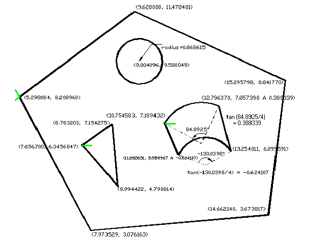
Each .VEC is a TEXT file containing the x and y co-ordinates of vertices of part profiles arranged in clockwise or counter-clockwise direction. If some segments of the profiles are arcs, bulge values will be attached to the starting vertices of arcs, or if the profile is a circle, center point and radius of the circle will be recorded. External profile of a part is stored in One example .VEC file will be described as follows:-
1 #
2 # AutoNEST V9 ENGLISH
3 # Shape Name = test1.vec
4 # First Line = InsertionPoint(x, y), ShapeArea, ShapePerimeter, ShapeRectLength,
5 # ShapeRectWidth, MinRectLength, MinRectWidth, DegreeOfMinRect
6 @ Vec not Compressed
7 9.346454 7.998023 51.850286 48.609869 9.997714 8.402318 10.014353 8.221825 -5.107422
8 9.62808011.478481
9 15.2957988.841770
10 14.6621403.673817
11 7.9735293.076163
12 5.2980848.208960
13 9.62808011.478481
14 @ Hole 1
15 12.7963707.857398 A 0.388339
16 10.7545837.189432
17 11.2826315.958967 A -0.624107
18 13.2540116.099591
19 12.7963707.857398
20 @ Hole 2
21 9.8040969.580049 C 0.868615
22 @ Hole 3
23 8.7832037.154275
24 8.9944224.798814
25 7.6567006.345684
26 8.7832037.154275
27 @ Leadin 1
28 4.838997 8.555070
29 4.982175 8.555070 A -0.280570
30 5.211919 8.398732
31 5.298084 8.208960
32 5.146448 8.096893 A -0.148813
33 4.951585 8.027744
34 4.817346 8.027744
35 @ Leadin 2
36 7.656700 6.345684
37 7.901215 6.345684
38 @ Leadin 3
39 10.754383 7.1857398
40 13.234154 7.1857398
(Note: The above line numbers are strictly for referencing purposes, they do not appear in the file.)
Description of .VEC File Format
Line 1 to 5 |
Lines start with "#" character denote comments. There is no limit to the number of comment lines. The 'AutoNEST V9 English', must be in one of the comment lines. The ‘V9’ reference number is used to check the different formats of (.VEC) files of different software releases. ‘English’ indicates what language version of current AutoNest you are using.
|
Line 6 |
'@ Vec not Compressed' is a file header identifier to indicate this vec part file has not been compressed. It will be followed by a section of an external profile of a part.
|
Line 7 |
9.346454 7.998023 51.850286 48.609869 9.997714 8.402318 10.014353 8.221825 -5.107422 First two values are always assumed to be the part’s Insertion Point. The X and Y co-ordinates in real numbers. No restrictions on the length of field. 3rd value is the Part Area. 4th value is the Part Perimeter. 5th & 6th values are the Length & Width of the “Enclosing rectangle” of the part in real numbers. 7th & 8th values are the Length & Width of the “Minimum Enclosing Rectangle” of the part. 9th value is the angle of rotation in order to obtain the “Minimum Enclosing Rectangle”.
|
Line 8-13 |
X and Y co-ordinates of each vertex of the external profile. X and Y co-ordinates in real numbers. No restrictions on the length of field.
|
Line 14 |
'@ Hole 1' is file header identifier to indicate the starting of an internal hole profile section of this part ‘1’ is the hole number of a part.
|
Line 15-19 |
‘A’ is an arc indicator. 12.796370 7.857398 A 0.388339
The first two real numbers are X- and Y- coordinates of starting point of an arc, the last real number is the bulge value of the arc. The ending point of the arc will be the first two real numbers at the following line. If the following line is starting with ‘@’, the ending point will lie in the first line of this section. This section means the first hole is a polygon with two arcs.
|
Line 20 |
‘@ Hole 2” indicates the starting of second hole profile section of this part. This hole number is 2.
|
Line 21 |
‘C’ indicates circle. 9.804096 9.580049 C 0.868615
The first two real numbers are X- and Y- coordinates of center point of the circle. The last real number is radius of the circle. That means the second hole is a circle.
|
Line 22 |
‘@ Hole 3” indicates the starting of third hole profile section of this part. This hole number is 3.
|
Line 23-26 |
A list of X- and Y- coordinates of each vertex of a polygon.
|
Line 27 |
“@Leadin 1” indicates the starting of one leadin / leadout section of part profile (in this example, it is for external profile).
|
Line 28-34 |
A list of X- and Y- coordinates representing the leadin / leadout lines or arcs. ‘A’ indicates Arc - same as the foregoing.
|
Line 35-37 |
Other leadin / leadout for part inner profiles. |
Notes on overall geometry of Part
| • | Each profile of geometry must be closed. |
| • | No stray or additional lines on the part profile(s). |
| • | No crossing over on each profile itself or between profiles. |
| • | Not more that 1500 vertices per profile, which includes the starting and ending vertices of arcs. |