|
|

|

|
|||
|
|
|
|
There is a function built into Router-CIM to provide a display of the tool along a cut path. This function is called Toolcheck. This display can be used for visual verification and actual measurement checks. To select, click on the Toolcheck icon on the Router-CIM toolbar.
Toolcheck uses only cut cycle blocks as input. A cut cycle block has only one tool description. Toolcheck performs the tooling display using the tool described in a single cut block. If a Sequence group is selected and the Sequence was developed using cycles containing different tools, only the first tool in the Sequence will be displayed. Use Toolcheck on individual Cut cycle blocks for correct tooling display.
The display of the tooling is controlled by four options. These options are Endpoint, Measure, Task, and Emulate. We recommend the use of Endpoint and Measure as the fastest, most reliable means of tool path verification.
The tooling geometry is on the Tool Check layer, and can be erased by selecting the Erasecheck icon off the Router-CIM toolbar. This is the only way to erase a Toolcheck!
The tool block is inserted at each Endpoint of the tool path. The inserts remain on the screen after completion of Toolcheck.
The tool block is inserted at Measured points along the tool path. The AutoCAD "Measure" command is used to develop each of the insert points. The spacing of the insert points is entered at the prompt "Enter Tool Check Spacing:". The inserts remain on the screen after completion of Toolcheck. If you wish to use this function to test your tool path, or direction of Cut, etc., click on the Toolcheck icon off the Router-CIM toolbar. You will be prompted to select objects, pick the tool path you wish to have checked. The next prompt gives you specific choices for the Toolcheck mode.
Select 'M' for MEASURE, and you will be prompted for the Toolcheck spacing; usually the default is ¼ of the tool diameter. This is the spacing of the Toolcheck circles as they move around the part. To use the default press <Enter>, or change the value, usually setting the spacing to the tool radius is sufficient.
The Toolcheck will then proceed around your part (see diagram below). There will be a circle the same diameter as the tool moving along the center of your tool path at the circles (tools) center point at the spacing you specified.
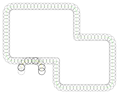
This is very useful for checking the direction of Cut on open shapes, where it is often difficult to tell if the direction of the Cut is correct.
Task
This option will allow you to use a custom task or macro you design to perform a custom Toolcheck.
You will be prompted at the command line with Enter Task Name: and you would type in the name of your task.
A default task would be TC. If you type in TC, the Toolcheck will continue.
The Emulate mode is to allow a block representing the tool to move across the tool path at specific intervals.
You will be prompted at the command line for the Tool Block Name. If you have made a custom tool block you want to use, type in the name now, otherwise Router-CIM will insert the block named TDIA.
Next, you are prompted to Select Emulation Spacing. The default is usually fine, however, you can set any spacing you desire.
The Starting Element is the next prompt, and you should select the lead-in, then you will be prompted for the Stopping Element, and you should select the lead-out.
Router-CIM will show the tool block moving around the part at the spacing provided.