|
|

|

|
|||
|
|
|
|
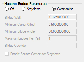
Nesting Bridge Parameters
Off
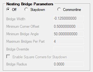
Setting this parameter to 'Off' will create a standard type of nest and place the parts on the sheet with all their tool paths. This is the default method of nesting with no advanced features. Typically this results in a separate tool path around each, individual part in the nest.
Staydown Nesting
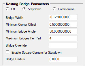
Staydown nesting will attempt to place the tool in the nest and leave the tool in the material as much as possible as it cuts around all the parts. This will typically create small bridges between the parts as the tool cuts around them.
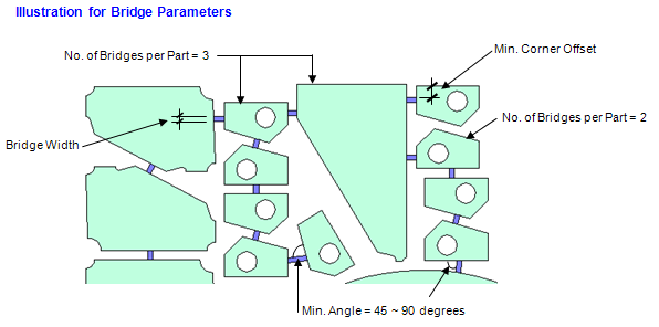
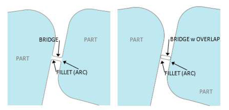
Bridge Width
Use this parameter to set the width of the bridges between the parts. These bridges can be a positive value so that there is a tab holding the parts together, or it can be a negative value so that the tool overlaps the starting point of the bridges.
Note: If you are using STAYDOWN with cutter compensation set to YES
1) You will need a bridge width set to the DIAMETER of the tool you are using plus the OVERLAP you are looking for. This should be a negative number.
2) Bridge Override needs to be set to 0.0
Minimum Corner Offset
The minimum corner offset is how far from the corner of the nested part the bridge can appear. You do not want the bridge on the very corner of the part, especially if you wish to use a negative tab that the tool will cut off. Typically you would put a number in there that would allow for the entire tool diameter to move from the tab to the corner of the part (so at least 1 tool diameter plus).
Minimum Bridge Angle
This is an angle between 45°-90°, to specify the minimum angle to consider for placing a bridge between two parts. Typically you would not want an angle that was too acute, or the bridge and resulting corner can become unsuitable for a tool to cut.
Maximum Bridges Per Part
There will often need to be several bridges on a part depending on the nest. This field limits the number of bridges that the nest can use to hold the parts together. This sometimes means that there will be more tool paths made if the number of bridges is too small. A good starting default is 4.
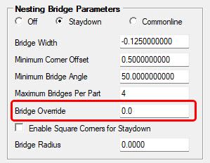
Bridge Override
This field defines the offset of the STAYDOWN cut path. This field should be left blank if you are using Cutter Compensation in your STAYDOWN cut knowledge set to NO or BOTH. If the Cutter Compensation in your STAYDOWN cut knowledge is set to YES, this should be set to 0.0.
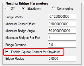
Enable Square Corners for Staydown
The STAYDOWN geometry created by Router-CIM Automation Suite has the rounded corner function in use by default. In order to change this function, select this option.
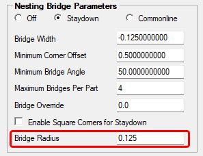
Bridge Radius
The STAYDOWN geometry created by Router-CIM Automation Suite can use an arc bridge when creating the bridge from part to part. Enter the radius of the bridge that is less then the diameter of the tool being used.
Creating the STAYDOWN Cut Knowledge
The Cut cycle should be Heli-Lead Center with no offsetting.
Note: In your DOIT file, do not cut the outside part layer. Turn that association off.
The DOIT file needs a knowledge to layer association to cut the tool stay down geometry created by AutoNest. You must make a knowledge called STAYDOWN and associate it to a layer called STAYDOWN. This one knowledge will be used to cut all materials in your job.
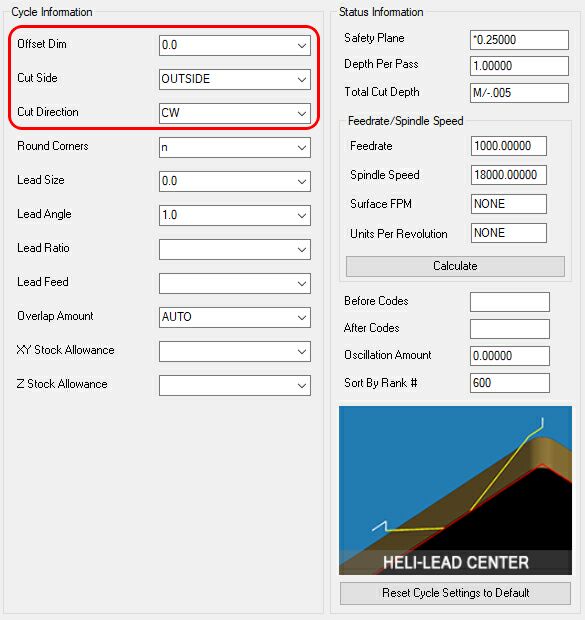
Cutter Compensation YES, NO or BOTH (Refer to the Cycle Information Column highlighted):
The Staydown knowledge can use cutter compensation with the YES, NO or BOTH. No changes need to be made when using NO or BOTH under cutter compensation. When using cutter compensation set to YES, make sure Bridge Override is set to 0.0 for an accurate cut path. This will allow the machine to offset the STAYDOWN tool path.
You will need to adjust the Cut Side parameter to 'Outside' as shown below:
If you need a different knowledge for each material in your job, you can make a layer / knowledge association formatted like this:
Knowledge name: MATERIAL CODE+STAYDOWN
Layer name: MATERIAL CODE+STAYDOWN
As an example, The ¾ MDF material has a material code of 75MDF and parts on this material will use a knowledge called 75MDFSTAYDOWN and their staydown geometry will be on a layer called 75MDFSTAYDOWN. The tool radius in this knowledge is used as the offset for part nesting. Other knowledges can cut this layer as well but the stay down geometry can only be cut on center and cannot be offset.
If you have parts on other materials, they will be cut using the regular STAYDOWN knowledge because they do not have a knowledge associated with the material code.
Small part cutting can still be used by making a knowledge that cuts the outside geometry and has a lower rank than the STAYDOWN knowledge. The small part cutting knowledge would be cutting the SML outside part layer. See 'Rename Outside Layers' section.
Common Line Nesting
Common Line will create a series of tool paths between the parts attempting to make the fewest tool path moves and still cutting all the parts. This means that the tool will be cutting parts on both sides of the tool path, instead of making one tool path around each individual part.
Note: Common Line nesting is designed for rectangular parts, rectangular parts with a defined Toekick feature. Toekicks with fillets (both outside and inside radius are considered).
Note: A Toekick is defined as a rectangular feature on the corner of the rectangular outside shape. The dimensions to be considered a Toekick are less then 4.0 inches (101.6mm) in X and 3.0 inches (76.2mm) in Y. If an outside is considered to have a Toekick, the outside shape will be adjusted to a rectangle and an L shaped piece of geometry will be created in the same method as the Commonline geometry and cut separately.

Commonline Toekick
The Cut cycle should be Center Line Cut or Center Line Ramp with no offsetting.
Note: In your DOIT file, do not cut the outside part layer. Turn that association off if parts are set to 'Nest Only'.
The DOIT file needs a knowledge to layer association to cut the common line geometry created by AutoNest. You must make a knowledge called COMMONLINE and associate it to a layer called COMMONLINE. This one knowledge will be used to cut all materials in your job.
If you need a different knowledge for each material in your job, you can make a layer / knowledge association formatted like this:
Knowledge name: MATERIAL CODE+COMMONLINE
Layer name: MATERIAL CODE+COMMONLINE
As an example, The ¾ MDF material has a material code of MDF75 and parts on this material will use a knowledge called MDF75COMMONLINE and their common line geometry will be on a layer called MDF75COMMONLINE. The tool radius in this knowledge is used as the offset for part nesting. Other knowledges can cut this layer as well but the common line geometry can only be cut on center and cannot be offset.
Parts in the same job on different materials will need a knowledge / layer association that matches the MATERIAL CODE+COMMONLINE format.
If you have parts on other materials that do not have a knowledge associated with the material code, they will be cut using the regular COMMONLINE knowledge.
The tool diameter in this knowledge is used as the bridge width for part nesting.
Small part cutting can still be used by making a knowledge that has a lower rank than the Common line knowledge and it cuts the SML outside part layer.
Consider the following nest of parts, cut with Common Line:
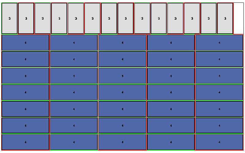
These parts are laid out according to size so that the common edges are matched. Looking at the same nest without the parts, shows the tool path motions:
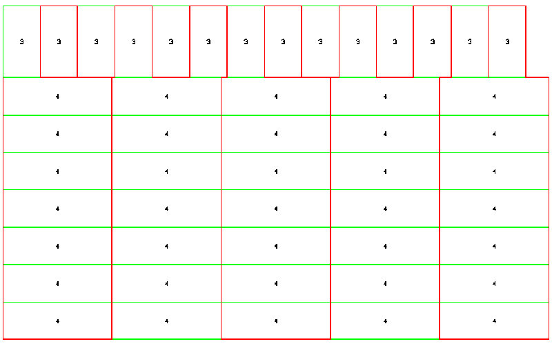
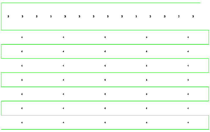
Here the hint of fact that there are really only two tool paths on the entire nest starts to show. If we isolate just the vertical tool path (red line shown) we can see:
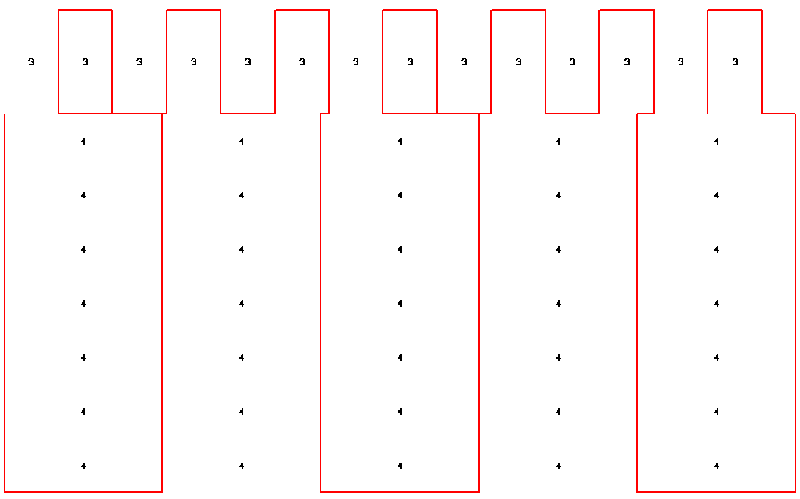
The above illustration shows that the tool path winds through the parts without lifting, cutting each of the vertical sections as it moves through the nest.
Further isolating the horizontal tool paths shows the rest of the tool path.
This is the horizontal path that cuts the rest of the geometry in the nest.
The end result being that with only two tool paths the tool is able to stay in the nest longer, eliminating the constant index moves from part to part and also is better able to maintain a more constant chip load, which keeps the tool cooler and makes it last longer. The result being a faster and more efficient process.