|
|

|

|
|||
|
|
|
|
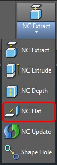
This icon is on the RCIM Solids toolbar. You may also access this function at the command line by typing ncflat. NCFLAT will rotate a part in space so that a selected face is pointing up to AutoCAD WCS (World Coordinate System). The part will also be extracted as if NCEXTRACT had been run.
This command is used only on Solids and Assemblies in AutoCAD or Mechanical Desktop. If you wish to use NCFLAT on a part of an assembly, it is recommended you copy the part and run the command on the copy. This allows you to use the Update Assembly command in Mechanical Desktop and have any changes to features, constraints, or dimensions reflected in the update.
To run the command:
1. Click on the icon and you will be prompted:
Select Face
Select the face of the part to orient up. Depending on the part, you may need to choose Next to select the proper face. The selected face will highlight. Hit Enter once you have the proper face selected.
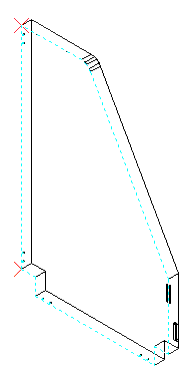
2. The face will appear as a blue dashed line with red X's appearing at the endpoints of the longest segment. At the command line you will be prompted:
Pick origin point <Longside>
Running object snaps will be changed to Endpoint for the next two prompts.
3. Choose the origin base point or hit Enter for automatic longest side selection. The longest side will be noted with a small X at the base point and a small > (arrow) at the x axis position.
If you chose a origin point, select a point that defines where the Positive X-axis should be.
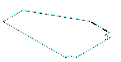
4. Then choose the move to point. It defaults to AutoCAD World 0,0,0. Running object snaps will be turned off for this pick. A drag view of the part will be shown. World 0,0,0 is the base point of the dragging.
The part will be moved to the move to point at the appropriate orientation in three-d space. The part will be extracted just as if NC Extract had been run.
Note: The longest side calculation only examines the ends of the outside profile. If the longest feature on the outside of the part is an arc, the ends of the arc will be lined up in the X-axis.