|
|

|

|
|||
|
|
|
|
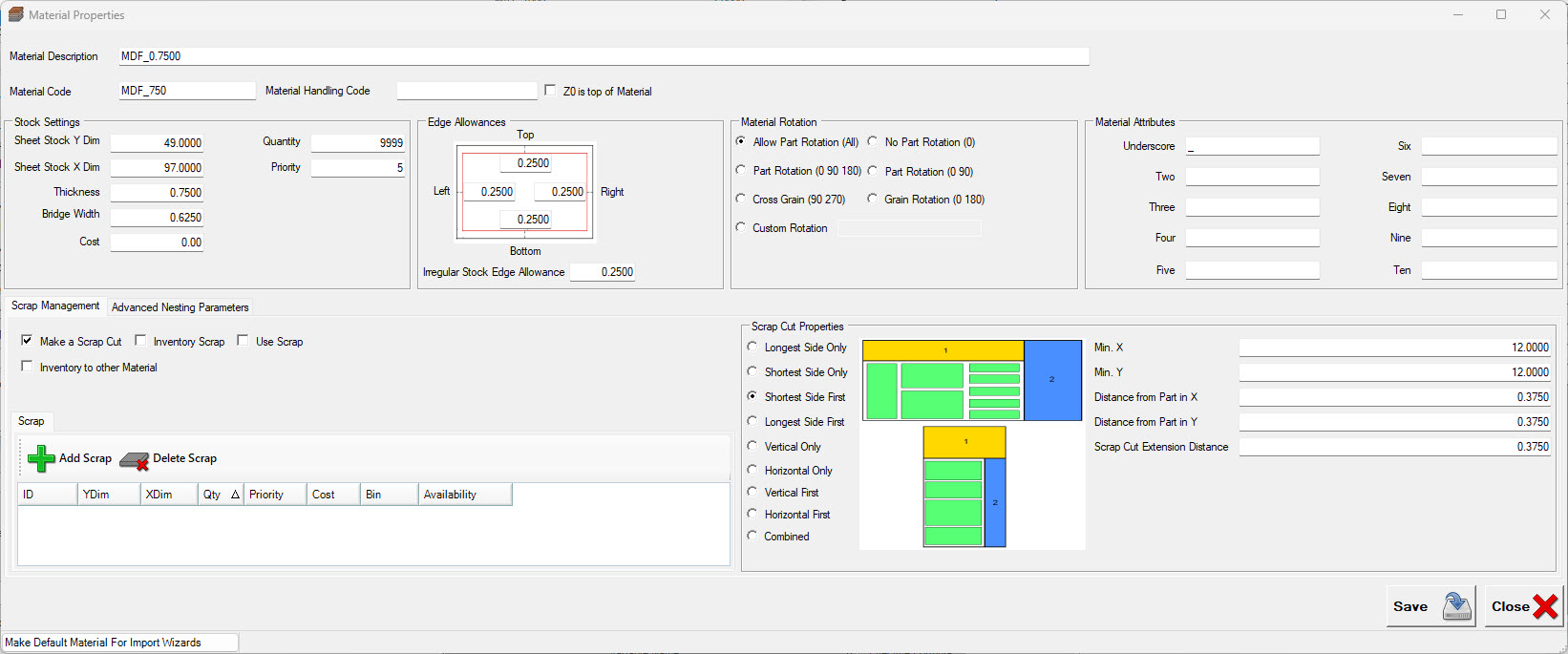
There are several default settings that will be present, but the main information that must be entered is:
•Material Description
•Material Code (unique to each material)
•Sheet Stock Y Dim
•Sheet Stock X Dim
•Thickness
Without these, the material cannot be saved.

Material Description (Required)
A text field describing the material. This description is most used in the labeling where the material description may be necessary. This field can be up to 255 characters. Any characters are acceptable except quotation marks.
Material Code (Required)
The Material Code is a field that accepts a 25 digit code. This code can contain letters, numbers, underscores ( _ ) and decimal points. This field needs to ALWAYS start with a letter or underscore. You cannot use spaces, and forward or back slashes Starting the Material Code with a number can result in issues later during job runs under certain circumstances.
Material Handling Code (Optional)
If your machine is equipped with an automatic material load/unload mechanism, you can enter the bunk number where the material is stored here and during the creation of the NC code file, the proper commands will be issued to grab the material from the correct location.
Z0 is top of Material
Typically Z0 is at the top of the spoilboard (bottom of part). Router-CIM Automation Suite automatically shifts all the tool paths and code to allow for the material thickness so that the tool paths are made properly for the material in the job. However, if you touch off your tools to the top of the material instead, check this box to avoid Router-CIM Automation Suite shifting all the tool paths.
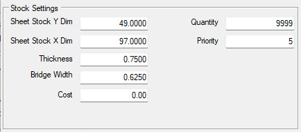
Sheet Stock Y Dim
The dimension of the material in the Y direction on the machine. This is always a positive number.
Sheet Stock X Dim
The dimension of the material in the X direction on the machine. This is always a positive number.
Thickness
The thickness of the material. This is always a positive number.
Bridge Width
This is the minimum distance to keep between parts when nested on the sheet. Typically this is set to at least the largest tool diameter in the job being run.
Note: To adjust the bridge width for a specific knowledge instead of the entire nest, click here to learn about 'Cutter Bridge'.
Cost
You may specify the cost of the material in this location. If you have advanced nesting, then you can also add multiple materials of the same type and list their cost, and allow Router-CIM Automation Suite to use the material sized based on cost per job instead of yield only.
Quantity
You may specify a number of sheets on hand in this location. The maximum number of sheets in 999. If you specify a lower number and the job runs out of material, you will be alerted that no suitable stock sizes are available.
Priority
You may specify a priority number from 1-10 for a material, and also for sub-materials of the same type. If you have advanced nesting, you can sort by priority, allowing the use of specific sizes of material as a preference.
You can specify areas to leave empty and have the parts offset from by filling in the edge allowances for each side of the sheet. Router-CIM Automation Suite will not nest any parts in this area. This is useful to keep parts for lining up exactly on an unfinished edge of a sheet and allow for any defects that may need to be avoided.
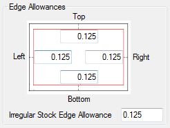
Left Edge Allowance
Default minimum distance to leave empty from the left side of the sheet to the nested parts.
Right Edge Allowance
Default minimum distance to leave empty from the right side of the sheet to the nested parts.
Top Edge Allowance
Default minimum distance to leave empty from the top side of the sheet to the nested parts.
Bottom Edge Allowance
Default minimum distance to leave empty from the bottom side of the sheet to the nested parts.
Irregular Edge Allowance
Default minimum distance to leave empty from the any side of the sheet to the nested parts.
Material rotation controls how parts are allowed to be placed on the nested sheet.
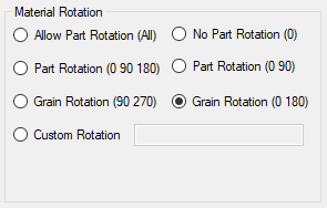
Allow Part Rotation (All)
Rotation set to all will allow parts to be rotated at any angle from 0-360° in 1° increments. See Part Properties under the Part Orientation section for how to override for individual part rotation considerations.
No Part Rotation (0)
Rotation set to 0 will not allow a part to be rotated from the angle it is drawn in. See Part Properties under the Part Orientation section for how to override for individual part rotation considerations.
Part Rotation (0 90)
Rotation set to 0 or 90 only from the angle it is drawn in. See Part Properties under the Part Orientation section for how to override for individual part rotation considerations.
Part Rotation (0 90 180)
Rotation set to 0, 90 or 180 olny from the angle it is drawn in. See Part Properties under the Part Orientation section for how to override for individual part rotation considerations.
Grain Rotation (0 180)
Rotation for consideration of grain will only allow a part to be rotated 180° on a nested sheet so that it is aligned with the grain of the material. Consideration should be given to the orientation of the part drawing when considering grain rotation. See Part Properties under the Part Orientation section for how to override for individual part rotation considerations.
Grain Rotation (90 270)
Rotation for consideration of grain will allow a part to be rotated 90° or 270° on a nested sheet so that it is aligned with the grain of the material for cross-grain. Consideration should be given to the orientation of the part drawing when considering grain rotation. See Part Properties under the Part Orientation section for how to override for individual part rotation considerations.
Custom Rotation
Rotation angle can be defined by the user. See Part Properties under the Part Orientation section for how to override for individual part rotation considerations.
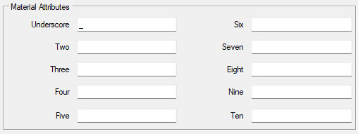
You can specify material attributes that you want to have saved with the specific material. The headings of these fields can be customized in the File/Settings under the Field Captions tab.