|
|

|

|
|||
|
|
|
|
Several styles of leads are supported with the Fourth Axis Interpolation cycle.
Arc Leads
There are three styles of Arc Leads, depending on the choices made in the Status Page.
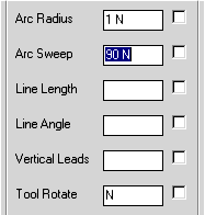
Horizontal Arc In
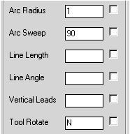
These settings in the Status Page produce the following results:
The tool is rotated to normal to the material before the lead in begins, then it moves in to the cut without rotating the tool. The Lead out moves away from the part without rotating the tool.
If a different lead in and lead out is required, two values separated by a space will apply the first value to the lead in and the second value to the lead out. For example, these settings:
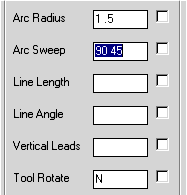
Produces the following result:
The lead in is the same; the lead out has changed. If you wish to suppress one or the other, put an N in place of a value as shown:
The N in the second position will suppress the lead out:
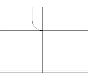
An arc lead in can only be created when both the radius and the sweep have been defined.
Horizontal Arc Leads with Tool Rotate
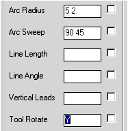
When you turn on tool rotate for the arc leads, the tool will sweep in on the arc. The following settings illustrate some of the actions that can be performed with the tool rotate option.
Produces the following results:
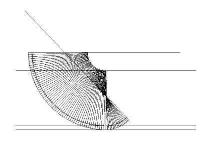
The tool is rotated 90 degrees to the shape, moves into the arc and sweeps by rotating the head as the tool center moves on the arc. In this example, the head is defined as 4 units long. On the lead out, the arc is smaller than the tool radius, so the reverse arc effect is shown as the tool pivots around 45 degrees before backing away from the part.
The tool rotate option can also be used selectively on the lead in and out by separating the values for the lead in and lead out by spaces. Tool Rotate only works on Horizontal Arc Leads.
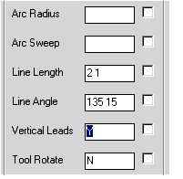
Vertical Arc Leads
When the vertical option is turned on, the arc is created vertically instead of in the XY Plane.
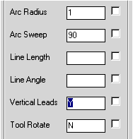
The results of setting vertical leads is shown below in the isometric view:
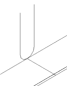
The tool is rotated perpendicular to the shape, then brought down onto the shape. As always, you can have different behaviors of the lead in and out by separating the values by spaces.
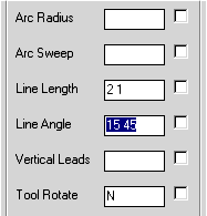
Horizontal Line Leads
The length of the line and the angle away from tangent required defines Line Leads. For Example:
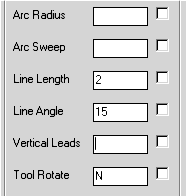
Produces the following results:
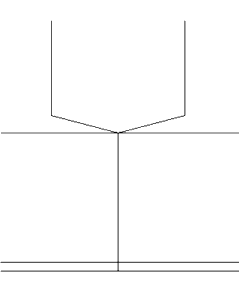
Like the arc leads, different values can be entered to achieve different results for the lead in verses the lead out.
Produces
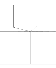
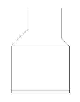
If the angle entered is greater than 90 degrees, the line will cut backwards to the lead point. This can be useful for entering slot cuts on the side of the part with a ramp in motion:
When these settings are cut on a simple line shape representing a slot cut, you get the following results:
Vertical Line Leads
Line leads can be vertical as well:
The lead in is a backward facing move, the lead out tapers off the end of the cut. Mixing vertical with horizontal only requires Y or N separated by a space as required.
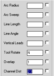
Channel Leads
Channel lead in and out is available as well. They are always vertical, and do not appear when cutting 3D geometry. When the geometry is open, the lead in will cut back along the contour until it gets to the lead in point, then it will cut forward along the shape. The channel out will cut to the end of the shape then back up along the shape up and out.
Overlap is often used with channel style leads, but it can be used with the other lead in styles as well. The Overlap parameter only works on closed shape. On open shapes you do not get an overlap.
When cut on an open and closed shape produces these results:
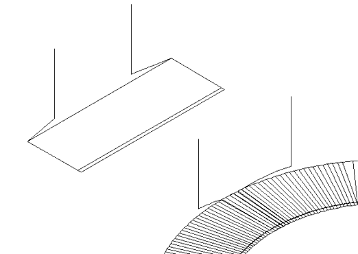
Notice that the leads follow the shape of the cut as they taper down into the shape. The overlap only occurred on the closed shape. The direction of the lead in and lead out reversed on the open shape.
Familiarity with the commands for you particular machine will ensure that you can recognize the code as generated by the post processor.
The use of specific aggregate tooling may require slight modification to these parameters, and CIM-Tech is available to assist you in configuring these parameters to suit your needs.