|
|

|

|
|||
|
|
|
|
There are some Parts that are so big that they cannot fit into any one stock. In another situation, there are Parts which by design have to be formed by joining two or more parts together. All these parts have to be “broken-up” into smaller pieces.
BreakPart command will enable you to “break” any selected part into multiple smaller parts. BreakPart is quite similar in function to SavePart but they are NOT the same.
In SavePart, the following files of each Part are created:-
.VEC , .DWG , and .DXF where
•VEC is a text file which record geometric information for a part, such as x, y coordinates of vertices, bulge values for arcs, center point, coordinates and radius for circles.
•DWG is the drawing file generated by AutoCAD when a part is saved as a Block /WBlock. This is to keep a true copy of the part geometry submitted to AutoNEST.
•DXF is a Drawing Interchange File format to assist in interchanging drawings between AutoCAD and other programs.
In BreakPart, the following files of each Part are created:-
•VEC , DWG & DXF of the original Part (same as SavePart)
•VEC of each individual “broken-up” Parts
•VEC of the combined “broken-up” Parts
For example, Part Name : ABC
ABC.VEC |
} |
ABC.DXF |
}Original Part (unbroken), same as SavePart |
ABC.DWG |
} |
ABC-1.VEC, ABC-1.dxf |
} |
ABC-2.VEC, ABC-2.dxf |
}.VEC of individual broken-up Parts |
ABC-3.VEC, ABC-3.dxf |
} |
ABC-N.VEC, ABC-N.dxf |
} |
ABC-$#.VEC ** |
}.VEC of the combined broken-up Parts |
|
}This file CANNOT be nested as it contains each and every individual broken-up parts / profiles. |
** IMPORTANT ** This file cannot be nested as it contains more than 1 profile.
When the BreakPart command is initiated either from the AutoNEST pulldown or icon menu, the following prompts will appear at the AutoCAD command prompt:
Break Part :
Select objects :
Break Part – indicate [Line/Distance/Automatic] <A>:
Break Part - Break into how many parts? <2> :
Part Name <> :
Part Quantity <> :
Require to save holes in Part? (Y/N) <Y> :
X nos. of Parts successfully created.
Select objects:
The Entity Select modes of AutoCAD are applicable here. You can type W (Window), C (Crossing), R (Remove) or simply pick the required entities to be saved as part.
If W (Window) is entered at this stage, a dynamic window will be formed to enclose the relevant geometry of the part. All the entities within the window will be saved as an AutoNEST part.
Break Part – indicate [Line/Distance/Automatic] <A>:
3 options to break the selected part are available here :-
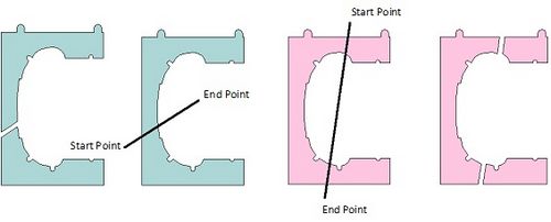
Enter L (Line) to indicate a cutting line interactively on the screen.
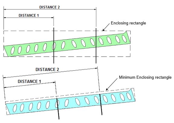
Enter D (Distance) to specify a distance from left-most point of the part.
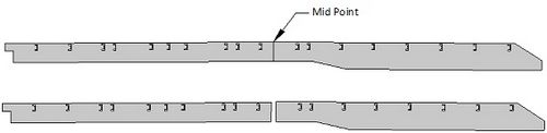
Press Enter (default) or A (Automatic) to break Part automatically at mid-point of the part.
If A (Automatic) is entered, BreakPart , the following prompts appear:
Break Part - break into how many parts? <2> :
If “2” is entered, BreakPart will automatically break the selected Part at mid-point of the Part. See above. The maximum no. of sub-parts created by this command is six (6).
Break Line – start point :
Break Line – end point :
To continue? (Y/N) <Y> :
If D (Distance) is entered, the following prompts will appear :
Break Part – reference to [Enclosing/ Minimum enclosing] rectangle <M> :
Distance from Left-hand Side (3000,6000) : (see below)
Part Name <> :
This is to prompt for the name of the new parts. (max. no. of characters allowed : 31, SPACE character is not accepted)
Part Quantity <1> :
Enter the quantity to be nested for this part.
Require to save holes in Part? (Y/N) <Y>:
This will enable the BreakPart command to save internal profiles of a part as holes, which may be used to nest other parts.
X nos. of Parts successfully created.
This prompt indicates the number of parts that have been created successfully.
No Insertion Pt. is being asked here as the Insertion Point is assumed to be in the middle of the part.
Conditions for Part Profile
Acceptable |
Unacceptable |
•Lines, Arcs, Circle, Rectangle, Polyline, Polygon and Spline entities
•External profile and internal holes profiles of a part must be closed.
|
•Block entity •Pedit-Spline and Pedit-Fit •Additional line/plines along the profile •Crossing over on each profile or between profiles •Part with more than 1500 vertices per profile (Inclusive of starting and ending vertices of arcs |