|
|

|

|
|||
|
|
|
|
If “Toolpath” or “common-line” is invoked or if the “Nest rectangle parts in regular grids” at @NEST_CONTROL (set in the ANEST.SYS) is set to “1”, an extra file with the filename extension of .SGD will be generated after nesting. .SGD will be generated besides .SYM and.SUM. Assuming that the task or job name is DEMO, the filename generated will be demo.sgd.
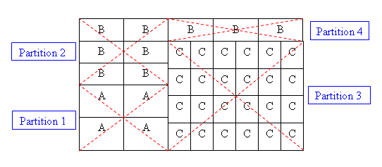
All the pertinent information of the nested results will be presented in “partitions blocks”. The layout below shows 3 distinct Parts (A,B & C) with 4 partitions blocks in total.
The format is as follows:
1 #
2 # AutoNEST V9
3 # SGD File Name = demo.sgd
4 # Layout from NestPro.EXE
5 # …
6 #
7 JOB = DEMO
8 No of Distinct Shapes = 3
9 Total No of Shapes = 37
10 Total No of Stock Sheet = 1 0
11 Encl Rect = (0.000000 0.000000) (42.854337 50.858266)
12 Stock Sheet = (60.000000 48.000000) x 1
13 Sum of Area of Shapes = 1543.50
14 (A 0.000000 0.000000 0.000000 200.000000 150.000000 2 2 1 0 0.000000 0.000000 0.000000 0.000000)
15 (B 0.000000 300.00000 0.000000 200.000000 100.000000 3 2 1 0 0.000000 0.000000 0.000000 0.000000)
16 (C 400.000000 0.000000 90.000000 100.000000 125.000000 4 6 1 0 0.000000 0.000000 0.000000 0.000000)
17 (B 400.000000 500.00000 0.000000 200.000000 100.000000 1 3 1 0 0.000000 0.000000 0.000000 0.000000)
(Note: The above line numbers are strictly for referencing purposes, they do not appear in the file.)
Line 1 to 6 |
Lines start with "#" character denote comments. There is no limit to the number of comment lines. The 'AutoNEST V9’ must be in one of the comment lines. The V9 reference number is used to check the different formats of (.SGD) files for different software releases.
|
|
Line 7 |
SGD filename. The key character here is the "=" equal sign. The words before it are purely descriptive but the name after the sign is important.
|
|
Line 8 |
Number of distinct parts. The key character here is the "=" equal sign. The words before it are purely descriptive but the value after the sign is important.
|
|
Line 9 |
Total quantity of parts nested. The key character here is the "=" equal sign. The words before it are purely descriptive but the value after the sign is important.
|
|
Line 10 |
Total number of distinct nested layouts. The key character is the "=" equal sign. The words before it are purely descriptive but 2 values (separated by space) indicate the no. of distinct nested layouts for regular and irregular stocks respectively.
|
|
Line 11-17 |
The first nested layout information.
|
|
Line 11 |
Enclosing rectangle of the first nested layout. The first pair of real numbers is the left-bottom point of the rectangle, the second pair is the length and width of the rectangle.
|
|
Line 12 |
Stock sheet size and the number of the repeated layout. Within brackets are the width and length of the stock.
|
|
Line 13 |
Sum area of parts nested in the current layout.
|
|
Line 14-17 |
A list of nested parts. Each line has the following format: (Part-name X Y Angle X_dist Y_dist Y_num X_num Grid_no Leadin_type Leadin_x1 Leadin_y1 Leadin_x2 Leadin_y2)
|
|
|
Part-name |
Name of the part. |
|
(X, Y, Angle) |
Transformation of the part, relative to the first layout’s left bottom point. |
|
(X-dist, Y-dist) |
The X and y grid spacing within a partition block. |
|
(Y_num, X_num) |
The number of rows and columns of grid, within a partition block. |
|
|
|
|
Grid_no |
Set to “1” by default. This flag holds the GRID_NO. |
|
Leadin_type |
Set to “0” by default as it is currently not in use. Common Grid Leadin type (a number from 3 to 13) for Common Cutting parts. For non-common cutting parts, it is 0, which means using part individual leadins, corner loops and microjoints |
|
(Leadin_x1, Leadin_y1) |
Set to “0” by default as it is currently not in use. The starting point of Common Grid Leadin (left bottom corner of leadin rectangle area) |
|
(Leadin_x2, Leadin_y2) |
Set to “0” by default as it is currently not in use. The ending point of Common Grid Leadin (right top corner of leadin rectangle area) |