|
|

|

|
|||
|
|
|
|
Setting up Knowledge for Horizontal Boring
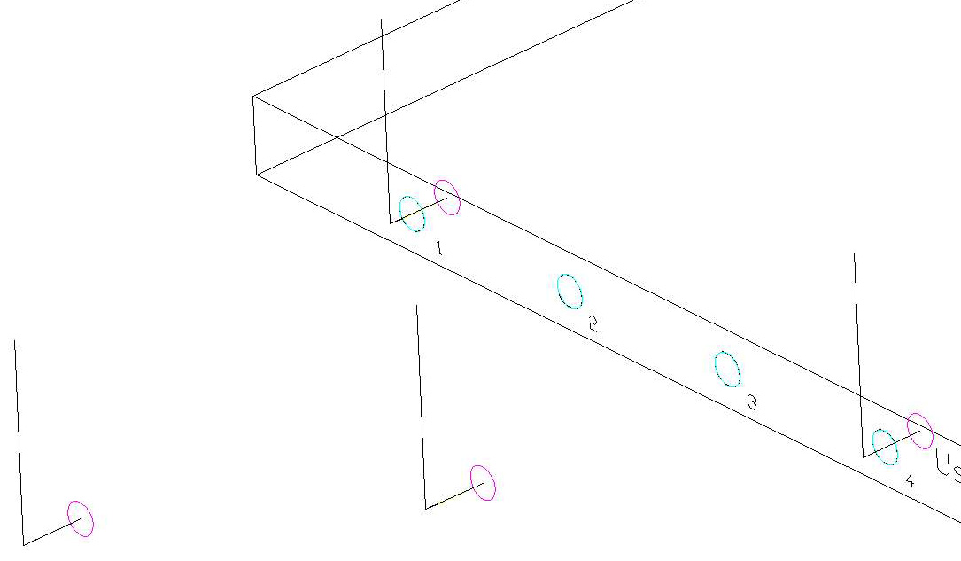
As mentioned earlier, there are 4 ways to drill horizontally, each being slightly different both at the machine and in Router-CIM.
Each of the types of horizontal boring use the Drill Motions cycle, and you must select the correct Tool Number for the face you are going to cut.
In addition, each uses the 4 Axis Safe position to move the drill up above the part between cuts.
Included in the Sample Drawing are 4 knowledges for each face. These represent the 4 different methods of cutting horizontally with the boring block and also use the correct tool numbers for each face.
This document will use the Front Side Drills as an example.
FrontSide1
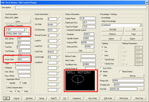
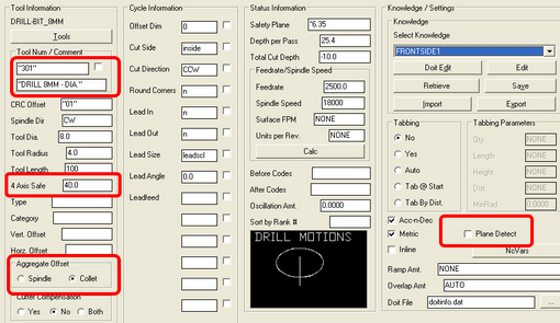
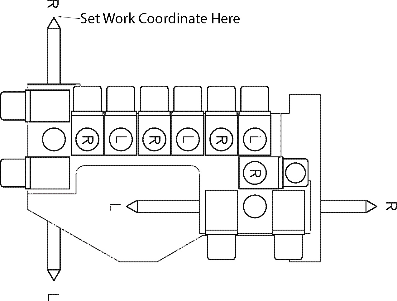
The FrontSide1 knowledge is a very basic boring knowledge and is the easiest to set up in Router-CIM, but not the easiest to set up at the machine.
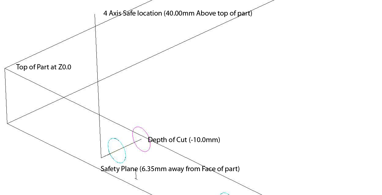
This knowledge uses a 4 Axis safe and has the Aggregate Offset set to Collet and Plane Detect is Not selected. When this knowledge performs a cut, the tool path shows up in a normal location with the cut inside the circle. The Collet setting keeps the cut in this location. The 4 Axis Safe setting makes sure the tool moves to 40.0mm above the top of the part both before and after the cut. The Safety Plane is now a horizontal move to 6.35mm away from the front face of the part.
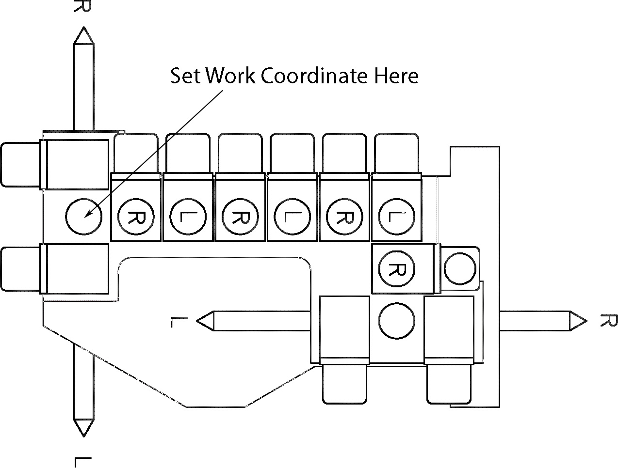
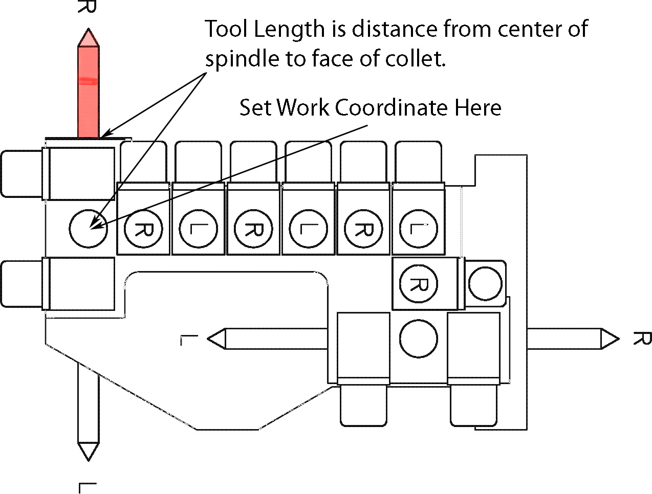
The important idea with this knowledge is that for the cut to be in the correct position on the part, the Tip of the drill bit must be set into the Work Coordinate at the correct X, Y location or else this tool cannot reach the correct point of the cut. When you touch off the tip of the vertical drills to the corner of the table, then the horizontal drill tips must be set there too.
FrontSide2
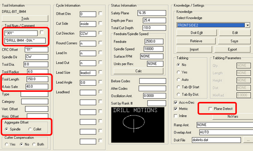
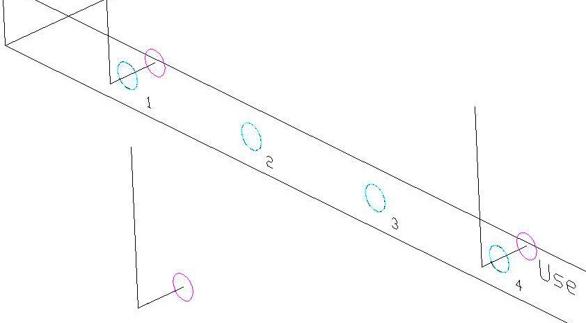
The FrontSide2 knowledge looks a little strange on the screen (it is away from the part) but is actually a little easier to use at the machine. The settings for this knowledge are:
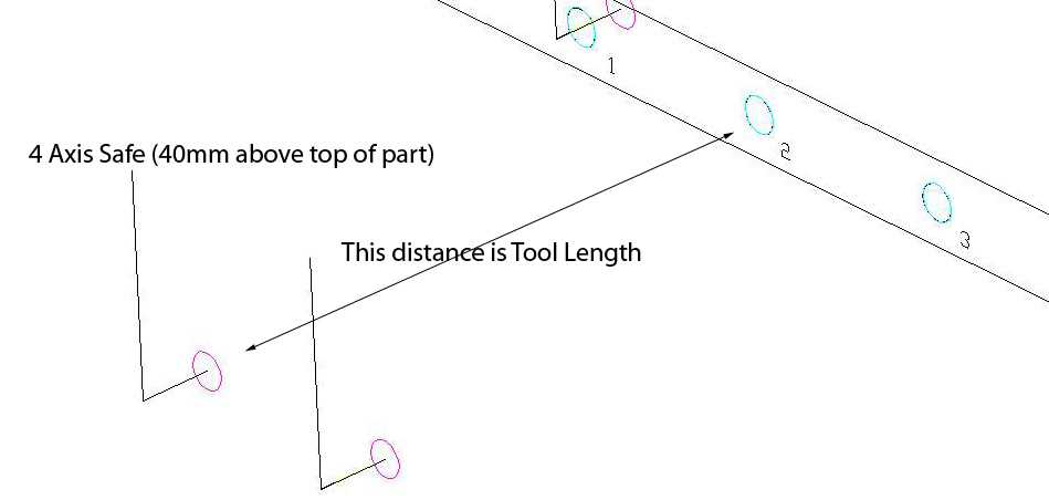
For this knowledge, you use the Tool Length to set the X, Y, offset from the center of the drill spindle and use the Spindle setting in Aggregate Offset. Plane Detect is not used for this method either.
In order for this to work properly, you must know the distance from the tip of the drill to the center of the drill block location (where the drill would be if it were a vertical drill). This is where the Work Coordinate would normally be set to. Then, put that distance into the Tool Length location. Router-CIM will move the tool path away from the part by that amount so that the TIP of the tool is actually at the right location. This requires no input on the machine operators side other than possibly informing the programmer of the length of the drill from the work coordinate location.
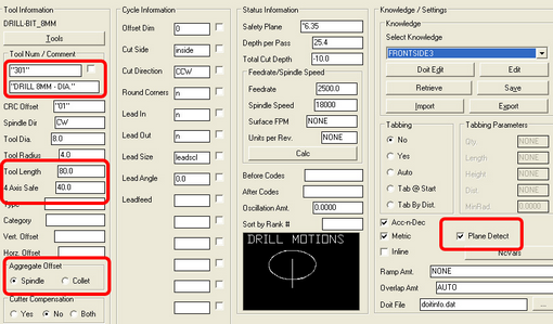
FrontSide3
This method is slightly different from the other two in that it will use Plane Detect and the code will be slightly different. There will also be a setting in the code for a horizontal offset to be input in the machine.
When using the Plane Detect option, Router-CIM will determine what plane the hole is being drilled on and will output a plane switch for the hole and offer another tool offset for the Horizontal Length. The tool path will look similar to FrontSide2, but the code will be very different.
The setting of the Tool Length is now from the center of the spindle to the face of the collet that the drill fits into. The distance from the tip of the tool to the face of the collet can be put in at the machine into a regular offset. This way if the drill length changes, a new program does not have to be created, only the offset has to be updated on the machine and the code run again.
The code generated for this cut would show the normal work coordinate, the Vertical H offset (in this case it is H21) and then the G18 plane command with another H offset for the length of the tool (in this case it is H41).
(DRILL 8MM - DIA.) G28 G91 Z0 M05 G90 T301 G00 G17 G54P1 X150. Y-156.35 M03 S18000 G00 G43 H21 Z59. <--------------- Vertical Height Set in this offset G18 G44 H41 <------------------- Horizontal Length Set in this offset Z9.45 Y-152.54 G01 Y-140.F2500. G00 Y-156.35 G00 Z59. H0
FrontSide4
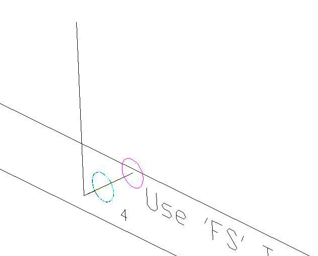
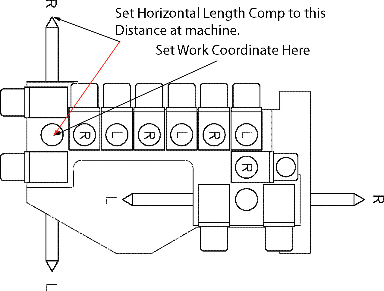
This last knowledge is almost exactly like FrontSide3, except that in since the tool path shows up in the normal cut position, then the amount put into the Horizontal Length Offset must be the distance from the tip of the too to the center of the spindle. This is only useful if the same length drills are always used and the required length is a known number for the operator. The programmer then does not need any data about the tool lengths and will generate a standard tool path and the operator is in total control over where the tool actually cuts.
Because the Aggregate Offset is set to Collet, the tool path looks normal:
The real trick here is to set the Horizontal offset correctly:
The code will look almost exactly like the previous sample, except that the X, Y values will be different because the tool path is in a different location.
(DRILL 8MM - DIA.) G28 G91 Z0 M05 G90 T301 G00 G17 G54P1 X200. Y-6.35 M03 S18000 G00 G43 H21 Z59. G18 G44 H41 Z9.45 Y-2.54 G01 Y10. F2500. G00 Y-6.35 G00 Z59. H0
|