|
|

|

|
|||
|
|
|
|
|
Project Cutting will create a tool path that is projected from a polyline(s) drawn above the part, down onto the surfaces or solid representing the part. Multiple polylines can be projected at one time. The resulting tool paths are vertical tool paths following the contour of the surface or solid.
The resulting tool path is on the top of the surface, but if you wish to move the tool path into the material, you can set a Stock Allowance of a Negative value to move the tool path down into the material. |
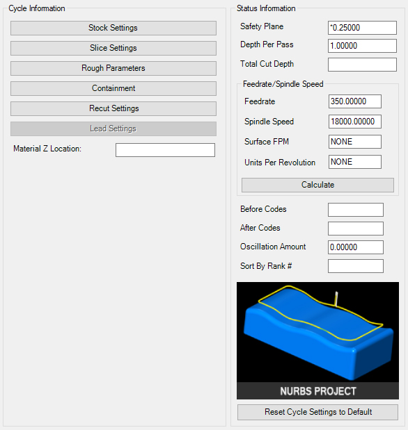
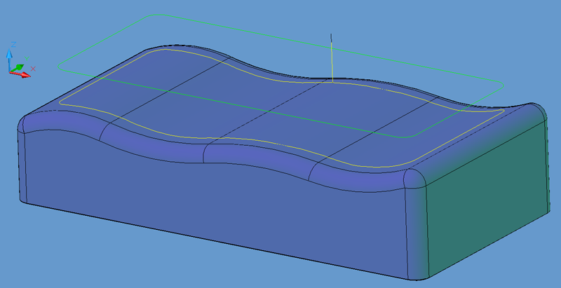
Shown is a tool path created with the default settings of the Nurbs Project cycle. Similar results can be obtained by selecting the cycle and simply pressing the cut button and selecting the solid model. When prompted at the command line:
Enter Surface Tolerance <0.00050000>:
Enter .005
Enter Surface Tolerance <0.00050000>: .003
You should see the same tool path as the picture above. The surface tolerance is the amount of deviation allowed for the tool path to follow the surface of the part as it breaks the moves up into small line segments for each pass. The smaller this number is, the more closely the tool path will follow the part contours, but the segments of the cut will be smaller, and thus produce more NC Code.
**Changing values in the cycle parameters may yield unexpected results with some settings or on some geometry. Examine the toolpath and NC Code carefully before running your machine tool if you change these default settings.