|
|

|

|
|||
|
|
|
|
|
The Nurbs Flowcut cycle is a contour following slicing cycle. Once the shape has been created, you would typically create two 2D Polylines to be used as flow lines that follow the contour you wish to cut. The Nurbs cutter will then prompt you during the cut to select these flow lines and create a tool path that follows them, on the surface or solid below.
You may use open or closed Polylines for the flow lines and each method is described.
The two Polylines used must be going in the same direction, as the flow cutting tool path will follow these Polylines. This is easily accomplished by using Geoshape and Start Point Edit on both flow lines, which will allow you to make them both become counter-clockwise Polylines starting from the same location. |
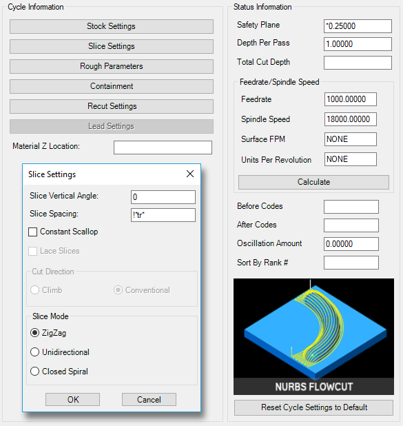
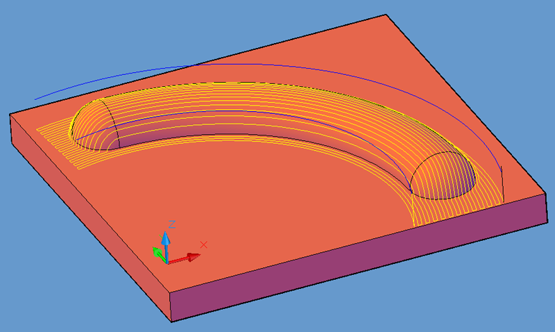
Shown is a tool path created with the default settings of the Nurbs Flowcut cycle on the MCADFLOW.dwg. Similar results can be obtained by selecting the cycle and simply pressing the cut button and selecting the solid model. When prompted at the command line:
Enter Surface Tolerance <0.00050000>:
Enter .005
Enter Surface Tolerance <0.00050000>: .003
You should see the same tool path as the picture above. The surface tolerance is the amount of deviation allowed for the tool path to follow the surface of the part as it breaks the moves up into small line segments for each pass. The smaller this number is, the more closely the tool path will follow the part contours, but the segments of the cut will be smaller, and thus produce more NC Code.
**Changing values in the cycle parameters may yield unexpected results with some settings or on some geometry. Examine the toolpath and NC Code carefully before running your machine tool if you change these default settings.