|
|

|

|
|||
|
|
|
|
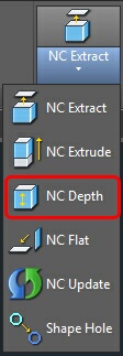
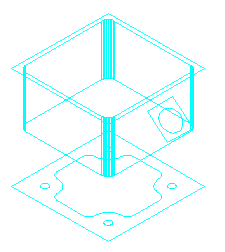
The NCDEPTH command allows the user to take existing shapes and link the material location and cut depth to existing entities, points in the drawing or specific values. The material location as well as the depth of the cut are defined using this command. For graphic feedback, the resultant shapes are moved up or down relative to the position of the polyline for the material location. The thickness of the shape is updated to show the depth of the cut. This depth of cut can be overridden by inserting a depth of cut in the Knowledge Editor. The cut depth can also be adjusted by a value. Use the / character before the number in the Knowledge Editor to add or remove from the depth of defined by NCDEPTH.
The NCDEPTH command has several options:
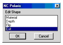
Material
The material location for a cut is defined by the location of the polyline. When you select Material, you are prompted for the shapes to edit. Select as many shapes as you wish. All shapes will be linked to the same material location. When you have selected the shapes, decide how to define the material location.
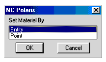
The ENTITY option prompts for an entity. Any entity that defines a point can be used to define the material location for a shape. If a 3D Solid object is selected, you will be asked to define the specific edge of the solid that should be used to define the material location.
The POINT option defines a specific point in WCS that defines the material location.
Regardless of how it is defined, by ENTITY or by POINT, the point does not change the work plane defined by the polyline. The polyline plane will be moved up or down to match the location of the defining point. Careful consideration should be made when cutting on the 4th and 5th rotational axis for proper positioning of the shapes.
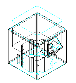
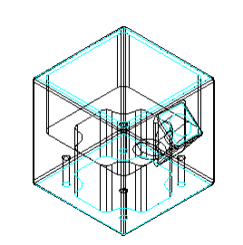
For example, this part shows a shape polyline that defines the pocket geometry of the solid model to cut. The part model was moved down after the shape was created. The shape is now too far above the part to be used. The shape location should follow the top edge of the solid model. The material option of the NCDEPTH command allows you to link the material location of the shape polyline to the geometry of the solid model.
When you choose the Material Option, by Entity, the first prompt asks:
Select the Shapes to Define New Material Location:
Select objects: 1 found
The shape above the part is selected. Choose the Entity option and select the solid model.
Select Material Object:
Solid Selected!
Select Edge on Solid
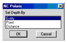
Since this is a solid model, you cannot select a specific edge until the solid is selected. The solid model is highlighted at this time, so select the top edge of the pocket hole.
The shape moves down to the top of the hole.
Depth
The depth of a cut is defined as the thickness of the polyline. The thickness is used by Router-CIM when you leave the Total Cut Depth blank, or fill in a plus or minus value that has a '/' <forward slash> in front of it. When blank, the exact thickness of the shape is used. When a Slash Value is used, it is added or subtracted from the actual part thickness. This can be used as an over cutting or undercutting technique.
In our example, the top shape is in position for the material location, and now we must define the cut depth. Cut depth can be defined in three ways:
Entity and Point work just like defining the Material location. Distance prompts for a simple depth. For example:
Select the top pocket shape
Select the Shapes to Define New Depth:
Select objects: 1 found
Select the Entity Option, then select the Solid.
Select Depth Object:
Solid Selected!
Select Edge on Solid
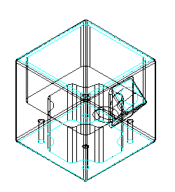
The solid edge selected is an edge on the bottom of the pocket shape. The polyline is automatically updated to show the new shape depth. The solid has been removed from this picture for clarity.
Flip
This option allows the user to flip the cutting direction of the polyline to the opposite side. Some shapes are easier to extract from the bottom or back side of a model and need to be flipped to cut properly.
Select the Shapes to Flip:
Select objects:
The selected Polylines will be flipped.