|
|

|

|
|||
|
|
|
|
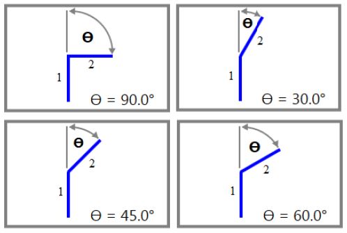
As the maximum machine angle changes the image to the right will adjust. Below are 4 examples showing the 90, 60, 45, 30 degree angles.
What is being represented in these images is that if the starting line segment is "1" and the next line segment is "2" that this is the angle that is being changed between those 2 line segments.
The maximum angle that can be inputted into this field is 90 degrees, because it is assumed that if the machine needed to make a change in direction that is greater than or equal to 90 degrees that it would need to decelerate to a feed rate of 0.
For Example:
In this scenario we are cutting an outside shape at a feed rate of 350 in/min. Some sections of the outside shape causes the machine to have a change in direction of 45 degrees, 50 degrees, 70 degrees, and 90 degrees.
The maximum machine angle for this machine is 50 degrees.
The 45 degree and 50 degree change in direction will have no deceleration, and the feed rate of 350 in/min will be maintained.
The 70 degree change in direction is greater than what our machine can do without needing to slow down. There will be some deceleration performed to the feed rate to accommodate this change in direction. The decelerated feed rate is calculated based on the cosine of the change in direction angle.
The 90 degree change in direction is assumed to cause our machine to decelerate to 0 in/min in order to accomplish this turn.