|
|

|

|
|||
|
|
|
|
There is a function built into Router-CIM to backplot NC Code files and produce on the AutoCAD screen the movements the tool made. Be aware that this will only read the NC Code file, not interpret your use of Cutter Compensation or how large a tool was, what size a hole was, etc.
To display the tool path on the screen, first start a new, clean AutoCAD. Then start Router-CIM inside the empty drawing.
Next type BACKPLOT at them command line and press <ENTER>

A window will appear where you can select your NC Code file. You should copy this file to the C:\Rcim_work folder as the backplot command may not work over a network path.
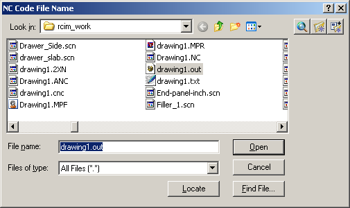
Once the file is selected, press <Open>
You will see another window looking for your backplot processor. If we have provided you with a special backplot file, it will be in the NCPOST folder and shown in this window, otherwise select the Generic.BI file.
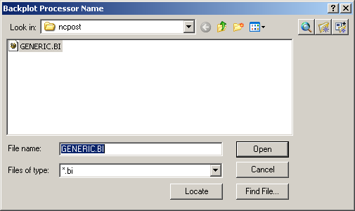
Once the file is selected, press <Open>
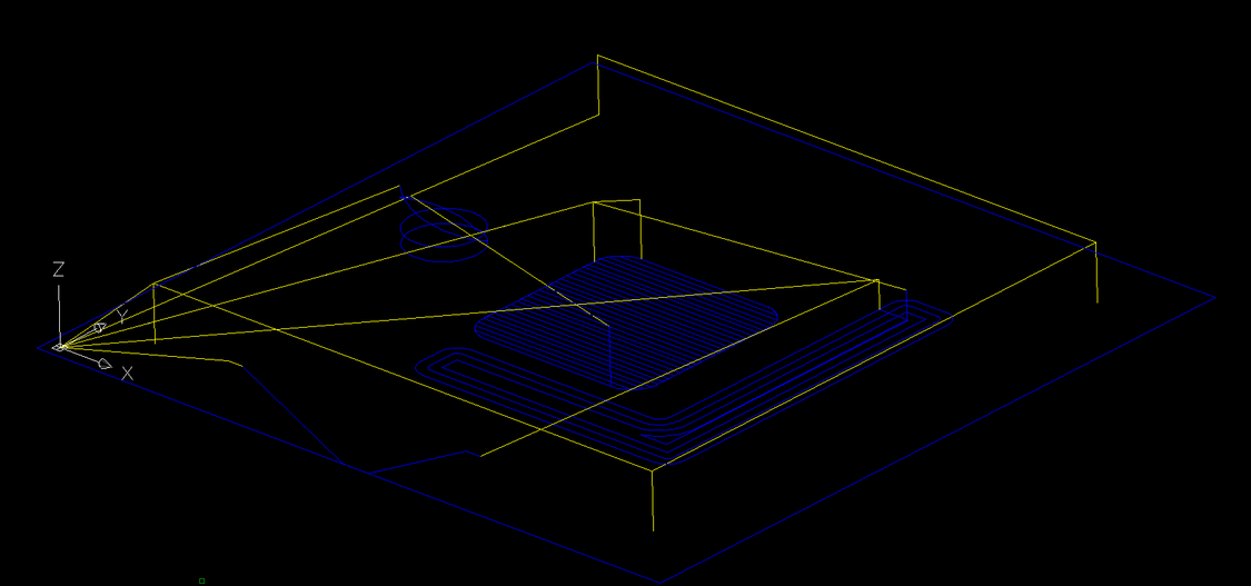
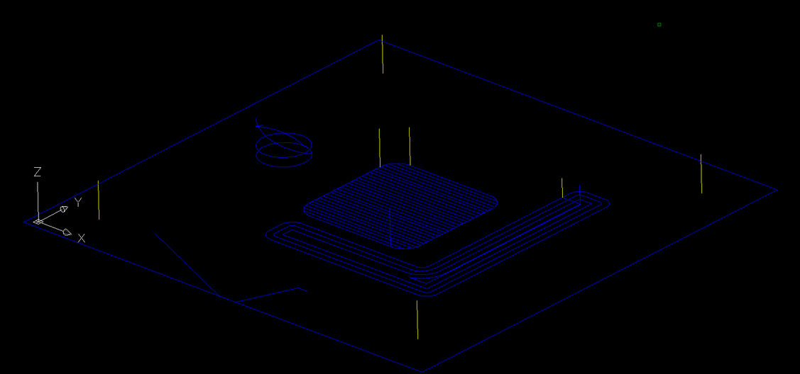
The file will then be read and the code will be translated into polylines and arcs on the screen, with the Index lines and the NC Text that was processed by the Backplot processor from your NC Code file.
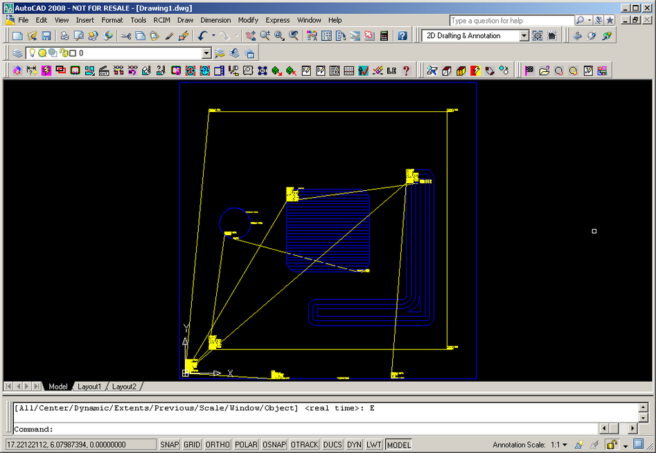
The real issue here is that these lines are the tools path...not your original geometry. So there are no circles for the drills to show what size they were, and the tool paths are offset or not depending on how you used Cutter Compensation in Router-CIM (or whatever software the NC Code came from). You will have to clean this drawing up quite a bit in order to re-create an actual part from it.
You can use the AutoCAD FILTER command to remove some of the bits you don't want from the drawing.
For instance, to remove all the text words from this drawing, you would first explode the drawing (as it is a block right now).
Next, start the Erase command.

At the Select objects prompt, type 'FILTER

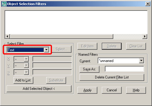
This will show the Object Selection Filters Properties window
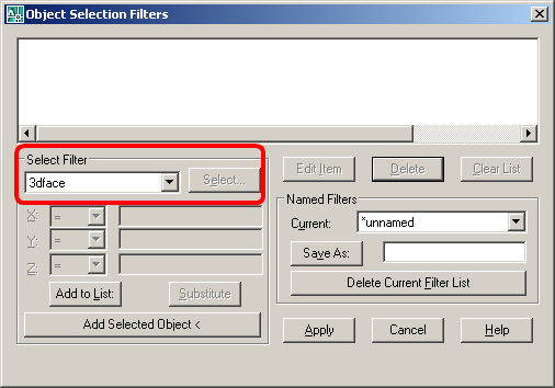
In the Select Filter list, scroll down and pick TEXT
Then pick on Add Selected Object to add it to the list above
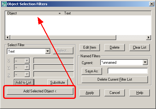
Then select Apply and you will be back at the command line.

At the Select object prompt, type in ALL

And press <ENTER>
This will remove all the text statements from the drawing and leave you with the tool moves and index lines.
If you erase the index moves, you have something closer to the part you cut.
This is not exactly your part, remember that all the tool moves could be offset from your original geometry to allow for Cutter Compensation. You also do not know what size the holes in the 4 corners are, so you would have to read the code and see if it uses a common tool that you know, or has a tool comment that would show you what tool was used, like this:
N5M08
N6(DRILL .25 DIA.)
N7G28G91Z0M05
N8G90T2006M06
N9T102
N10M03S18000
N11G00G17G55X1.Y11.
N12G00G43H6Z1.
This code shows that a .25 drill bit was used, so you could draw some .25 diameter circles where the drill points are.
Looking at the backplotted geometry next to the real geometry shows the differences.
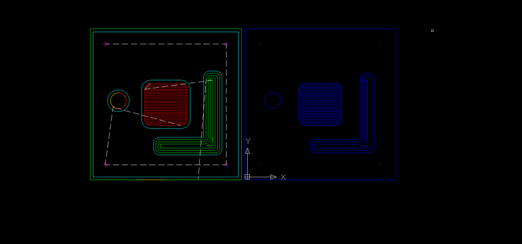
From here you can see that the outside geometry needs to be offset in and the inside cuts need to be offset outwards to recreate the actual part. You will need to do some work to make a part from code, but the general outline of what was cut will be shown.