|
|

|

|
|||
|
|
|
|
When changing the tool parameters, it is important to know the definition of the parameters you need to change to get the desired results. Not all of these parameters will have to be changed with every tool, but you should be familiar with the settings and their definitions.
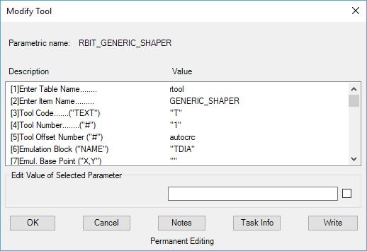
(01) ENTER TABLE NAME...This is the table name of the tool list and normally is never changed.
(02) ENTER ITEM NAME... This is the name of the tool as it will appear on the tool list. You should try to keep the name format of similar tools similar to each other, so they are easy to find in the list (refer to current list for reference). You cannot use spaces, or special characters in this version of the tool name. Only Underscore and Hyphen are allowed.
(03) TOOL CODE... This is the code put out for individual tools, usually the tool definitions are accounted for in the post processor so changes are not necessary. Unless you are directed to change this parameter in your application notes, you should not change this parameter at all.
(04) TOOL NUMBER...This is the default number of the tool as it appears in the Control Panel. If you have a tool that is always the same number, place the number here so that it is the default. The number must be set inside quotation marks in order to generate the correct code.
(05) TOOL OFFSET NUMBER... This is the same as the offset number on the Control Panel. Normally you will not need to change the field from 'autocrc' unless you wish to have a specific offset number for a particular tool. This will output as the "D" value with the number you specify in this field.
(06) - (17) EMULATION BLOCK NAME, AND EMULATION XY SCALES... These values control the block to insert and the size of the Tool Check tool. You can show a detailed Tool Check by drawing a 3D tool and storing it as a Block in your default or current drawing. Put the block name in the Emulation Block Name field. During the Tool Check command, that block will be inserted. A task called Tdsize will use the tool's diameter for the emulation X and Y scale factors. These are for advanced use of the Tool Check function and are not normally used for regular programming.
(18) TOOL ROTATION... This is the same field that appears in the Control Panel as Spindle Dir. If you have counter-clockwise spindles, you should change this field when you are using CCW bits in your spindle. This field generates an M03 or M04 code for clockwise and counter-clockwise normally.
(19) TOOL TIP DISTANCE TO ZERO... This is the distance that you need to compensate for if you have a tool whose tip is not flat. If you touch off the tip of the tool to zero, but there is an angled or rounded surface to the end of the tool, such as a drill bit or a ball mill, you can input the distance to the desired cutting surface here.
(20) DESCRIBE TOOL... This will be the description of the current tool as it will appear in the NC code file (of your router supports comments). This field can hold any description or character, however it must be enclosed in quotation marks.
(21) TOOL DIAMETER...This is the field that appears in the Control Panel as Tool Diam. The diameter of the tool input here should be the outside diameter of the carbide.
(22) TOOL LENGTH... This is the same field that appears in the Control Panel, if you wish to set the default Tool Length input a number in this field.
(23) TOOL RADIUS...This is the same field that appears in the Control Panel as Tool Rad.
(24) TOOL CUT DEPTH... This is the same field that appears in the Control Panel as the Depth Per Pass field. This is the maximum depth you wish the tool to be able to cut in the Z direction in any single pass, thus extending tool life.
(25) - (26) These fields are reserved and should not be edited in normal use.
(27) This field should normally be set to "Y" and should not be edited in normal use.
(28) MACHINE CUTTER COMPENSATION... This is the field where you can specify the default value for the Cutter Comp. Selection in the Control Panel. Valid entries are "Y", "N", or "B" for Yes, No, or Both. Please refer to the section on Cutter Compensation for further details.
(29) FEED DISTANCE TO MATERIAL... This is the point at which your machine tool switches from rapid traverse to programmed feed rate. This field is set to .1 and should not be set any lower than this! The machine tool will rapid to this point and then the next line of code will have to use a feed rate code if it is going to enter the material.