|
|

|

|
|||
|
|
|
|
#
# AutoNEST V9
# File Name= ANEST.SYS
#
@SHP_APPROX
| 25 | # Minimum vectors |
| 5 | # Maximum No of loops |
| 25 | # Minimum concave area increment (in percentage) |
| 8.0 | # Total Area Increment (in percentage) |
| 2 | # Minimum Arc (in percentage) |
| 0.08 | # Global tolerance factor (wrt largest enclosing rectangle edge) |
3.0 # Local tolerance factor (wrt neighbouring edge)
0.0 # Circle & arc accuracy degree, range from 0.0 to 9.0
100 # Minimum vectors per spline
@NEST_CONTROL
3 # 0: No Nestb 1: Normal + Nestb 2: Nestb Only 3: As indicated in UI
30 # Nestb maximum group number
1 # Nestb minimum average number per group
0.1 # Nestb flexible ratio (0.0 to 0.1)
0 # 1: Nestb keep grid, 0: break grid
0 # Allow / Disallow high priority parts nested in the hole of low priority parts
0 # Nest rectangle parts in regular grids (only when all parts are rectangle)
2 # 0: Stock priority- system decides based on best utilization; 1: Follow stock priority strictly;
2: Follow stock priority strictly but allow merging of stocks wherever possible.
0 # 1: Follow part priority strictly; 0: Part priority - system decides based on best utilization
500 500 # Maximum number of distinct stock sizes, ir-stock sizes
0 # Maximum number of distinct parts (in the future)
60 40 # Stocks Merging Control: merge only when utilization is < N1%(rectangles) or N2%(non rectangle)
@MORE_NEST_CONTROL
400 400 # Best Yield Option: Maximum no. of distinct Parts and Stocks
200 # No. of pins per row, min.=100, max.=500 (higher value may give better result but will slow down nesting)
1 # SPCN - 1: Whole part must be inside Small-Part Zone; 2: CG must be inside Small-Part Zone
0 # SPCN - The percentage of extension allowed for Small-Part zone (eg 10)
@REMNANT_CONTROL
1 # 0 : Fill whole stock with filler parts.
# 1 : Fill stock with filler parts up to the basic qty edge)
0.10 # If last stock (after nest the basic qty parts) remains 10% or less,
# fill up the rest of stock with filler parts.
0 # 1 : Rectangularisation of remnants, 0: No
1 # 1 : Retain profile of original Stock; 0:No
remnant # Suffix for Remnant Stock (Ir-Stock)
IR-remnant # Suffix for Remnant of Ir-stock
0.5 # Gap between Part & Remnant (factor of cutting gap)
@SIMPLIFY_CONTROL
200 # minimum number of vertice of polygon to do simplification in PIP
# adjust higher will slow down nest but will get better PIP pattern
0.05 # Part simplification ratio to remove concave gaps (0.00 - 0.10)
@BRIDGE_CONTROL
140 # Maximum angle between vectors that is valid for Corner Offset consideration
0 # 0: Draw bridge as per normal. 1: Draw bridge with overlap
0.97 # To draw commonline (toolpath) using Part Enclosing Rect. Ratio of Part Area
(against Enclosing Rect) must be this value or more.
0 # To draw commonline (toolpath) using Part Enclosing Rect. 0.6 (or specified) of Length & Width must
be orthogonal
0.001 # To draw commonline (toolpath). Tolerance Value for Rectangle
@TEXT_DISPLAY_CONTROL
4 # Tolerance angle for Part Labelling
0.80 # Text Height scale factor (in order to fit text within a Part's width)
0.95 # Text Height scale factor (in order to fit text within a Part's length)
0.15 # Auto Text Height – Factor of Text height/Part width
@OTHER_CONTROL
0 # Output Part color code (for debugging) {0: As in Sysdata, 1: Nesting Logic, 2: SPCN}
0 # Display stock layouts strictly in packing order (for debugging)
1 # Fill layout space at the end of packing for every stock (last PIP) (for debugging)
0 # Label part by part name-0, by priority-1
0 # 1: Parts & Task directories default to same; 0: Remain separate directories
1 # 1: Excel reports created during Nesting; 0: No Excel reports created during Nesting
0 # 1: Text(Partname, Taskname...) in reports to be in uppercase; 0: Text case to remain as original
@SHP_APPROX
Under this heading are the parameters that influence how a polygon profile is being approximated. Generally, the rougher the approximation, less number of vectors will be used to represent the geometry. Fewer vectors will decrease the workload of the nesting process.
The user can judiciously adjust the following parameters for maximum performance during the nesting process.
Profile approximation is therefore more effective when the original number is large. However too much approximation may also lead to profile distortion that provides inefficient nesting.
1st Parameter : Minimum Vector (for Polygon Approximation= 25)
It is the minimum number of vectors in one polygon profile before part approximation routine is allowed.
Generally, a polygon profile with less than 25 vectors when approximated would produce a new profile that is quite different from the original part. Therefore a limit is imposed to prevent unexpected results.
2nd Parameter : Maximum No of Loops (= 5)
The maximum number of times the subroutine processes through all the vertices of a profile. It acts as a safety counter to ensure that the subroutine will terminate properly.
However it is to be noted that complex profiles require more approximation passes. Too many passes will make the process longer, too little will not give an efficient approximation. A judicious number will be derived from the user’s experience.
3rd Parameter : Minimum Concave Area Increment (in percentage= 25)
This parameter has an important role in controlling the amount of “cut-through” in concave portion of the polygon profile. It is the incremental area allowed for all the “cut-through” in concave approximation.
Increase in the parameter will result in greater amount of "cut-through" during approximation.
Note that another parameter, 'Minimum Arc', does play a similar role in controlling the amount of "cut-through" as this control parameter. 'Minimum Arc' will be discussed later in the section.
4th Parameter : Total Area Increment (in percentage= 8)
As the routine approximates a polygon profile, the net area will be expanded. A limit in area increment is therefore necessary before the new profile is grossly different from its original profile.
This value is the additional percentage in area increment that is allowed for approximation subroutine.
The approximation will be terminated once the area increment exceeds the value of parameter or in the case when there is no more approximation possible.
Do not confuse this parameter with the ‘Minimum Concave Area Increment’ discussed previously. The present parameter is using the total area of profile after approximation in deciding the quitting of subroutine. The previous parameter is used during the concave portion of the profile,
5th Parameter : Minimum Arc
This parameter is not valid for current version.
6th Parameter : Global Tolerance Factor (= 0.08)
7th Parameter : Local Tolerance Factor (= 3.0)
8th Parameter : Circle & Arc Accuracy Degree ( = 0.0)
For parts with a very high number of vectors or arcs, this parameter will enable you to control the “roughness”. The higher the value, the higher the accuracy of arc vectorization. The default value 0 will give a reasonable result to most jobs. Bear in mind that the higher the value, the more time the nesting will take.
9th Parameter : Minimum vectors per spline ( = 100)
This parameter enables you to set the minimum no. of vectors to be created upon converting a SPLINE entity in .DXF to .VEC. The maximum no. of vectors, after conversion of spline is 1,000. This parameter is used in ConvertPart (DXF2VEC).
@NEST_CONTROL
There are 12 parameters under @NEST_CONTROL where the first 5 parameters control the NESTB nesting engine. Each of them are explained below :-
1st Parameter :
0 |
Do not use the exhaustive nesting engine, NESTB |
1 |
Use the normal nesting engine OR NESTB depending on the TASK (.job) |
2 3 |
Always use the exhaustive nesting engine, NESTB. As indicated in the UI. By default, option 0 is used for nesting. If the “Extended” check-box is marked, then option 1 will be employed. |
2nd Parameter :
30 |
Increasing this number will enable more Tasks to be submitted to the NESTB nesting engine. At the same time, less of “similar” shaped parts will try NESTB. |
3rd Parameter :
1 |
Default is “1”. This is the lower limit of the average number of individual parts in a Task for NESTB. |
4th Parameter :
0.1 |
This means that NESTB is able to extend beyond 10% from the nested pattern when considering if a part or a group of parts are suitable. |
5th Parameter :
0 |
If there is a grid pattern consisting of identical shapes in the nesting result. NESTB engine will ignore the regularity of the grid, and will carry out any necessary operation to make the final result tighter. |
1 |
If there is a grid pattern consisting of identical shapes in the nesting result. NESTB engine will not break the grid, and retain its regularity in the final output. |
6th Parameter :
0 |
Do NOT allow high priority parts to be nested into the hole of low priority parts |
1 |
Allow high priority parts to be nested into the hole of low priority parts |
7th Parameter :
0 |
Nest rectangle parts using generic nesting engine. |
1 |
Nest rectangle parts in regular grids for better common-line tool-path generation (only when all parts are rectangle) - using RNEST engine. |
8th Parameter :
0 |
Stock Priority - Based on the priority specified, AutoNEST decides based on best utilization. |
1 |
Follow strictly Stock Priority as defined in .JOB. |
2 |
Follow stock priority strictly but allow merging of stocks when the stock utilization is less than the specified values set in the 12th parameters under @NEST_CONTROL |
9th Parameter :
0 |
Part Priority - Based on the priority specified, AutoNEST decides based on best utilization. |
1 |
Follow strictly Part Priority as defined in .JOB. |
10th Parameter :
500 |
The maximum number of distinct regular stocks defined in a task. |
500 |
The maximum number of distinct irregular stocks defined in a task. |
11th Parameter:
0 |
The maximum number of distinct parts defined in a Task (currently NOT in use). Currently this value is fixed at 1000. |
12th Parameter:
60 |
Stocks Merging Control : merge the stocks if the utilization is less than 60% - applicable for rectangles. |
40 |
Stocks Merging Control : merge the stocks if the utilization is less than 40% - applicable for non-rectangles. |
@ MORE_NEST_CONTROL
There are 2 parameters under @MORE_NEST_CONTROL. They are explained below :-
1st Parameter :
400 400 |
Applicable for “Best Yield” and “Lowest Cost” options in Multi-Stock Control, the maximum no. of distinct Parts and Stocks allowed in any one Task. The default is 400 for both. |
2nd Parameter :
200 |
This parameter is used in the “Special Pins Nesting” routine incorporated into the nesting engine. No. of pins per row, min.=100, max.=500 (higher value may give better result but will slow down nesting) |
3rd Parameter :
1 |
This parameter is used in the Small-Part Nesting Control (SPCN) engine. 1 denotes the Part must be inside the Small-Part zone; 2 denotes the CG of the Part must be inside the Small-Part zone. |
4th Parameter :
0 |
This parameter is used in the Small-Part Nesting Control (SPCN) engine. This parameter is the percentage of extension allowed for Small-Part zone. 0 means no extension. 10 means Small-Part zone is extended by 10% |
@REMNANT_CONTROL
There are 7 parameters under @REMNANT_CONTROL. Each of them are explained below :-
1st Parameter :
0 |
Always fill-up the whole stock with filler parts. |
1 |
Fill stock with filler parts, only up the edge of the “Basic qty” parts. |
2nd Parameter :
0.10 |
If last stock (after filling in the basic quantity) remains 10% or less, then fill up the rest of the stock with filler parts, otherwise do not. |
3rd Parameter :
0 |
Created stock Remnants will NOT be rectangularized or broken up into rectangles. |
1 |
Created stock Remnants will be rectangularized and saved into individual rectangles. |
4th Parameter :
0 |
Do not include the original stock profile for the created remnant. |
1 |
Include the original stock profile for the created remnant. |
5th Parameter :
$REM |
Suffix for remnant stock name. The names of the remnant stocks automatically created are :- Taskname_$REM1-1.stk, Taskname_$REM2-1.stk, Taskname_$REM2-2.stk …. and so on. The naming convention is as follows :- *_$REM(LAYOUT_NO)-(NO) where * is the taskname and “$REM” the suffix. |
6th Parameter :
IR-remnant |
Suffix for remnant of ir-stock The names of the remnant(s) of ir-stock automatically created are :- Taskname_IR-remnant1-1.stk, Taskname_remnant1-2.stk, Taskname_IR-remnant2-1.stk The naming convention is as follows :- *_ (LAYOUT_NO)-(NO) where * is the Taskname and “IR-remnant” the suffix. |
7th Parameter :
0.5 |
Gap between the remnant and the Parts. (factor of the cutting gap) |
@SIMPLIFY_CONTROL
There are 2 parameters under @SIMPLIFY_CONTROL. Each of them are explained below :-
1st Parameter :
200 |
Minimum number of vertices of polygon to do simplification in PIP, adjusting higher will slow down nesting but will get better PIP pattern. |
2nd Parameter :
0.05 |
Part simplification ratio to remove concave gaps (0.00 to 0.10). Higher value will make nesting fast, but waste more stock material; lower value will use more nesting time, but waste lesser stock material. |
@BRIDGE_CONTROL
There are 5 parameters under @BRIDGE_CONTROL that controls Auto-Bridge.
1st Parameter :
140 |
The maximum angle in degrees formed by 2 vectors that is valid for Corner Offset consideration specified by user. If the 2 vectors formed an angle larger than this parameter, then the program will ignore the Corner Offset. (range 90~180 deg) |
2nd Parameter :
0 |
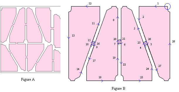
Draw bridge as per normal. See Figure A. |
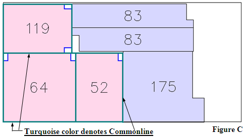
1 |
Draw bridge with overlap. This is to enable the cutting tool path to overlap at the bridge entrance /exit. (See Figure B - follow the sequence of the arrows) |
3rd Parameter :
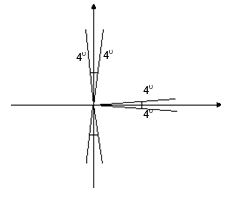
0.97 |
To draw commonline (toolpath) using Part Enclosing Rect. Ratio of Part Area (against Enclosing Rect) must be this value or more. See Figure C. |
4th Parameter :
0.6 |
To draw commonline (toolpath) using Part Enclosing Rect. 0.6 (or specified) of Length & Width of Part must be orthogonal. |
5th Parameter :
0.001 |
To draw commonline (toolpath). Tolerance Value for Rectangle. This is the tolerance value Commonline will consider when determining if a part is rectangle. |
Commonline (toolpath) will consider Parts 119, 64 & 52 as rectangles and then add “L” for toekick.
Area of Part/ Area of Enclosing Rect must be 0.97 or greater.
Whereas Parts 83 & 175 are not considered as rectangles because their Area of Part/ Area of Enclosing Rect < 0.97.
The toolpath for Parts 83 & 175 will be the same as their profile -NO commonline.
@TEXT_DISPLAY_CONTROL
There are 4 parameters under @TEXT_DISPLAY_CONTROL that controls the display of text labeling.
1st Parameter :
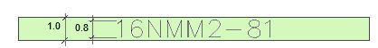
4 |
Tolerance angle for Part Labelling. Text orientated within 0 to 4 degrees reference to the X/ Y axis will be snapped to the nearest axis. See below. |
2nd Parameter :
0.8 |
Text Height scale factor – applicable if “Reduce Scale to Fit” is set to ON (in order to fit text within a Part's width). Especially for thin narrow parts. See diagram below for illustration. |
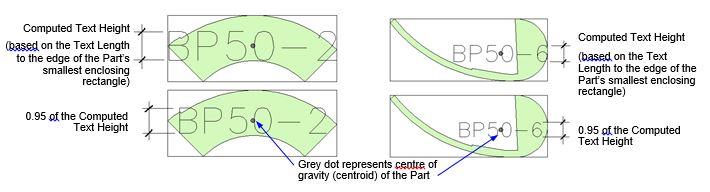
3rd Parameter :
0.95 |
Text Height scale factor – applicable if “Reduce Scale to Fit” is set to ON (in order to fit text within a Part's length). This scale factor is based on the computed Text Height. See diagram below for illustration. |
4th Parameter :
0.15 |
‘Auto’ Text Height is calculated based on the smaller width of the Part’s enclosing rectangle multiply by this factor. |
@OTHER_CONTROL
The parameters under this heading are mainly for debugging purposes. Please do not change any one of them. However you can set both the PART and TASK directories to default to the same by changing the 5th parameter to “1”.